How does an incremental encoder work?
How does an incremental encoder work?
"S7-200 SMARTStepping motor with dynamic control"
In the previous two articles, we introduced stepper motors and stepper drives. We know that the stepper motor itself does not have a feedback device. In some occasions that require precise control, it needs to be used with feedback devices such as encoders. In order to make this tutorial closer to practical engineering applications, our experimental device is equipped with an incremental encoder. In this article, we will get to know the incremental encoder.
This lesson includes the following content:
1. What encoder?
2. Classification of encoders;
3. The structure and working principle of incremental encoder;
4. Connection of incremental encoder and PLC;
1. What is an encoder?
The English name of the encoder is "encoder", which is a sensor that can convert distance (linear displacement) and angle (angular displacement) into electrical signals and output them. Encoders are usually used in industrial motion control where accurate position control is required. For example, in a machine tool system, a stepper motor is used to control the position of a tool, and an encoder is used to detect and feedback the actual position. With the encoder, the control system can form a closed loop.
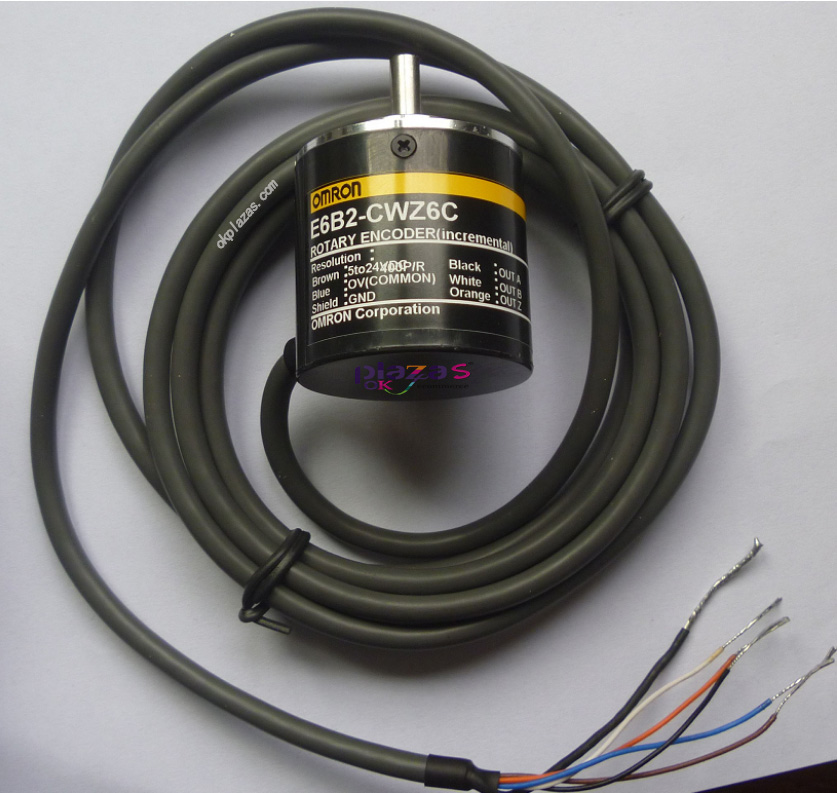
The following picture is the physical picture of Omron's incremental encoder E6B2-CWZ6C:
2. Classification of encoders
According to different working principles, encoders can be divided into optical encoders, magnetic encoders, inductive encoders, capacitive encoders, and so on.
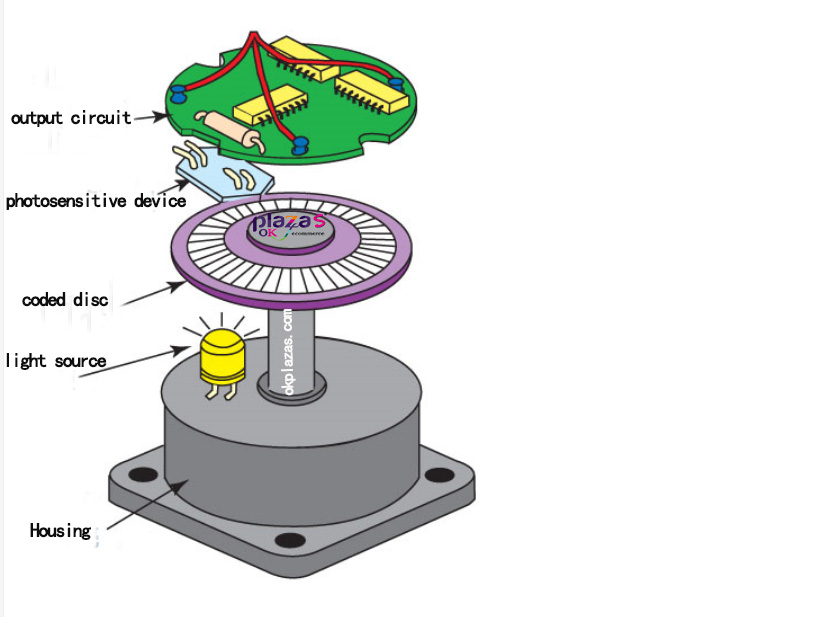
The most common is the photoelectric encoder.
The composition of the optical encoder includes: Shaft, Code disk, LightSource, Output circuit, shell and connecting flange, etc., as shown in the figure below:
According to the structure of the code disc, the encoder can be divided into incremental encoder and absolute value encoder
Device.
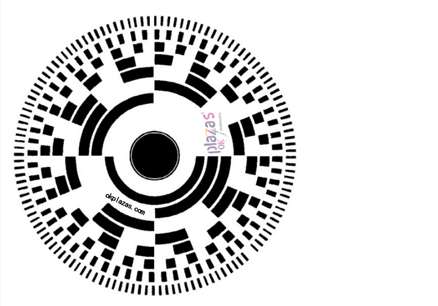
Absolute encoder, the English name "Absolute encoder", outputs a set of binary numbers. Its code disk is divided into many concentric channels, and each channel is called a "code channel". Each code channel has a separate output circuit to represent a binary
The bit of the system. Through the combination of binary bits, a value can be uniquely determined. The code disk of the absolute encoder is shown in the figure below:
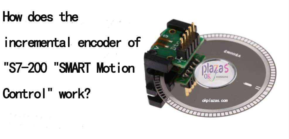
3. The structure and working principle of incremental encoder
Incremental encoder, the English name "Incremental encoder", its code disc is divided into light and dark gratings of equal size. As the code disc rotates, the receiving end will detect the change of light 0 and 1 and convert it into The electrical pulse signal is output externally. The pulse signal is connected to the high-speed counter module, and by counting the number of pulses, the size of the displacement can be determined (because the number of pulses sent by the encoder per revolution is fixed).
The code disk of the incremental encoder is as follows:
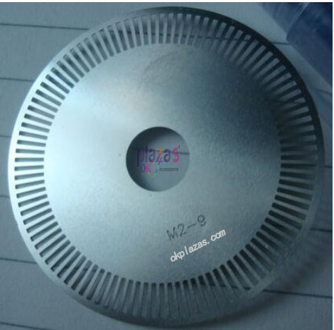
The above-mentioned code disc structure has only 1 circle of grating, and only 1 electric pulse signal output in the case of using one light source. This often cannot meet the actual requirements, because in practical applications we often need to detect whether the motor is rotating forward or backward, sometimes even Need to perform zero detection.
To detect the forward and reverse rotation, there are two methods.
Method 1: Use a code wheel with a grating and two light sources.
By adjusting the distance between the code disc grating and the position of the two light sources, the phase A signal and the B phase signal are separated by 1/4 cycle (the phase angle difference is 90 degrees), so that the occurrence of the A phase signal and the B phase signal can be judged Sequence to determine whether to rotate forward or reverse. The schematic diagram of this method is as follows:
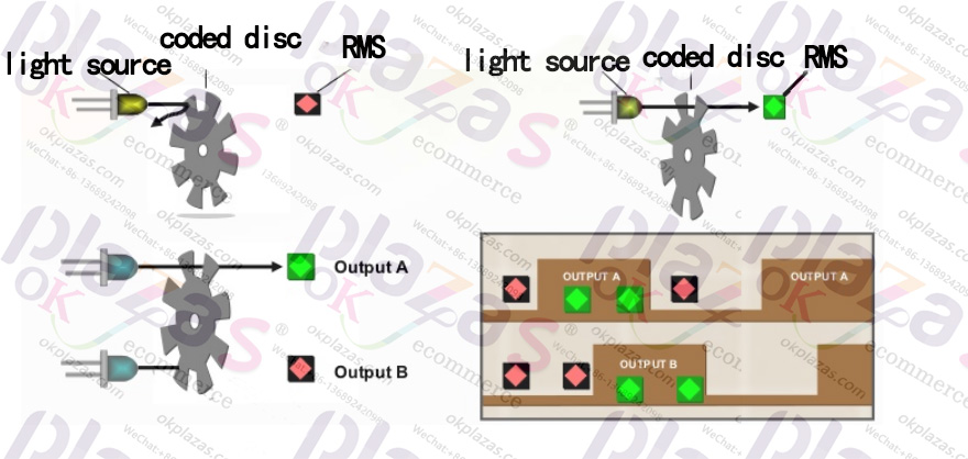
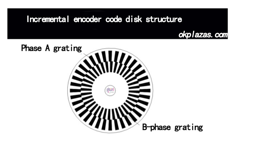
Method 2: Use a code wheel with 2 gratings and a light source.
This method uses a code disc with 2 gratings, the outer ring is A-phase grating, the inner ring is B-phase grating, and the interval between the two gratings is 1/4 width, as shown in the following figure:
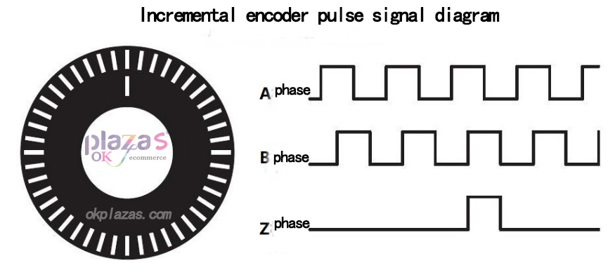
In addition to the A/B phase, in practical applications, some encoders also provide zero-point pulse signals. The zero-point pulse signal is to add a concentric grating hole on the code disc, and a pulse is sent out every revolution. The output signal is called Z-phase (Zero), as shown in the following figure:
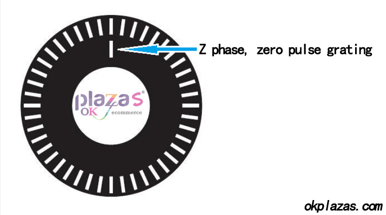
in this way, the output signal of incremental encoder A-phase/B-phase/Z-phase is shown in the following figure:
4. Connection of incremental encoder and PLC. The pulse signal output by incremental encoder needs to be connected
Connect to the high-speed counter of the PLC. Some PLC CPU modules integrate high-speed counters
(For example, S7-200 SMART, S7-1200 series), the output signal of the encoder can be directly connected to the integrated high-speed counting channel of the CPU module; some CPUs themselves do not integrate high-speed counters (such as S7-300/1500 series) ,This
In this case, a special high-speed counting module is required Piece.
Well, about the VIP course "S7-200SMART Motion Control Stepper Motor" first introduce so much, if you are interested in this course, you can click the link below to view the course content.
-
The principle and application field of Autonics panel products (handling)
 June 12, 2021
 -
New product launch SRH1 series single-phase SSR with integrated heat sink
 June 12, 2021
 -
New product launch SRH1 series single-phase SSR with integrated heat sink
 June 12, 2021
 -
Otto protection grade IP69K new product launched Ø18mm cylindrical (SUS316L housing) photoelectric sensor BRQT series
 June 12, 2021
 -
Autonics adds shading motion mode sensor
 June 12, 2021