Talking about the signal circuit output mode of incremental encoder
Talking about the signal circuit output mode of incremental encoder
Talking about the signal circuit output mode of incremental encoder
We know that encoders can be divided into incremental encoders (Incremental Encoder) and absolute encoders (Absolute Encoder). The main difference between the two is the structure of the encoder and the form of the output signal. Incremental encoders output pulse signals, while absolute encoders output binary values. For incremental encoders, there are many types of output circuits. When using a high-speed counter to count the pulse signals of the encoder, you must first figure out the encoder's output type to correctly wire and debug. Today in this article we will talk about the output circuit of the incremental encoder.

The output circuit of the incremental encoder includes collector output (Collector Output) type, voltage output (Voltage Output) type, push-pull output (Push-Pull Output) type and line driver output (Line Driver Output) type. The core component of the output circuit is a triode.
We know that the triode has three poles: Base, Emitter and Collector
Polar (Collector). The collector output circuit of the encoder is based on the emitter of the triode.
Terminal, a circuit where the signal is output from the collector. Since the triode is divided into PNP and NPN, the corresponding
Yes, the collector output circuit of the encoder is also divided into PNP and NPN.
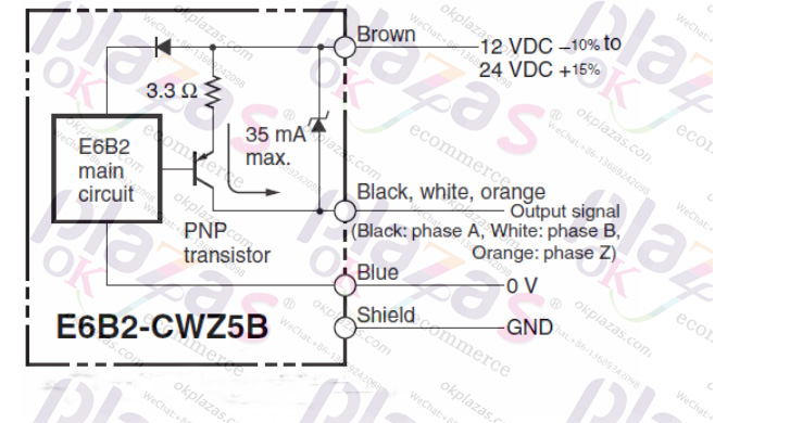
The picture below is the collector output circuit (PNP type) of Omron E6B2-CWZ5B encoder. You can see that the power supply (+12V or +24V) of the encoder is connected to the emitter of the transistor through a 3.3 ohm resistor, and The pulse signal (A/B/Z) is output from the collector:
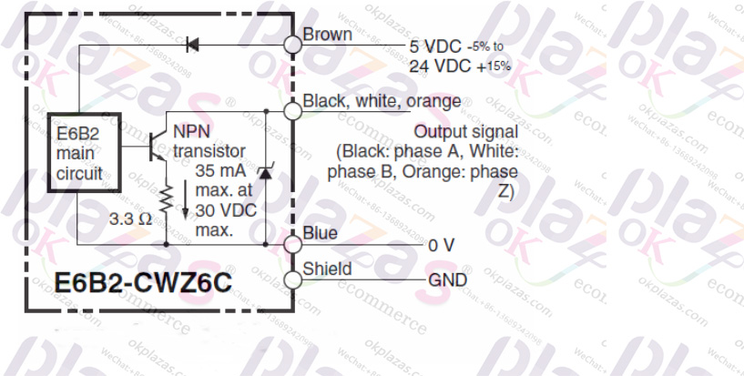
The NPN collector output circuit is similar, except that the emitter (common end) is connected to 0V, such as the following E6B2-CWZ6C output circuit:
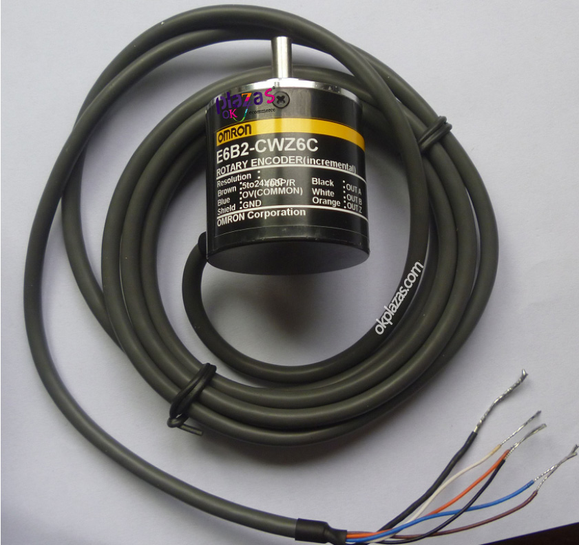
The following is the physical picture of E6B2-CWZ6C:
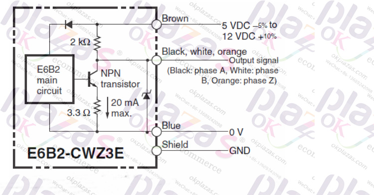
In the voltage output type, a pull-up resistor is connected between the collector of the NPN transistor and the power supply, so that the output voltage of the collector will be clamped in a stable range. The picture below is the voltage output circuit of Omron E6B2-CWZ3E:
The Push-Pull Output circuit consists of two transistors, such as T1 and T2 in the picture below.
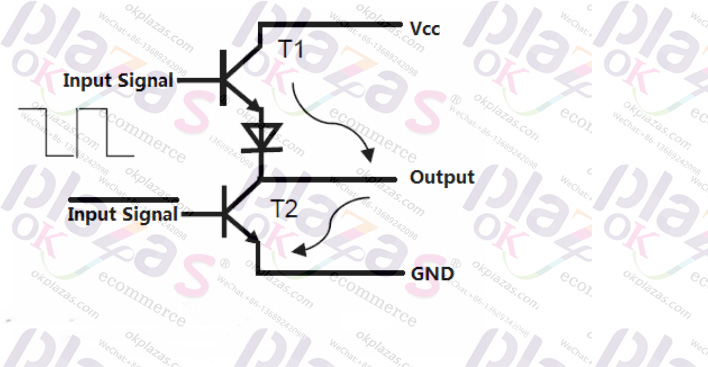
The two transistors of the push-pull output accept the input signal and the inverted signal of the signal respectively. When the input signal is 1, T1 is turned on, and the inverted signal of the input signal is 0, so T2 is cut off; the same , When the input signal is 0, T1 is off. At this time, the inverse of the input signal is 1, so T2 is on; it can be seen that the push-pull output circuit can output the positive and negative phases of the signal (such as A and A complement), and its resistance The interference ability is relatively strong, suitable for long-distance transmission.
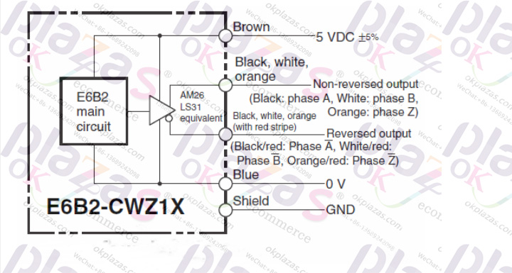
The Line Driver Output circuit uses a dedicated output chip, and the output conforms to The RS422 standard differential signal has stronger anti-interference ability and is suitable for occasions with higher transmission speed and longer distance. The picture below is the line driver output circuit of Omron E6B2-CWZ1X:
Ok, let’s talk about the circuit output mode of incremental encoders first. Related reference articles: What is the difference between an absolute encoder and an incremental encoder?
-
The principle and application field of Autonics panel products (handling)
 June 12, 2021
 -
New product launch SRH1 series single-phase SSR with integrated heat sink
 June 12, 2021
 -
New product launch SRH1 series single-phase SSR with integrated heat sink
 June 12, 2021
 -
Otto protection grade IP69K new product launched Ø18mm cylindrical (SUS316L housing) photoelectric sensor BRQT series
 June 12, 2021
 -
Autonics adds shading motion mode sensor
 June 12, 2021