How does the encoder accurately measure the position of the motor
How does the encoder accurately measure the position of the motor
How does the encoder accurately measure the position of the motor
1. What is an encoder
Encoder is a device that compiles and converts signals or data into signal forms that can be used for communication, transmission and storage. Encoder angle
Displacement or linear displacement is converted into electrical signals. The former is called a code wheel and the latter is called a yardstick. He is a commonly used motor positioning device in industry,
Can accurately test the angular displacement and rotation position of the motor.
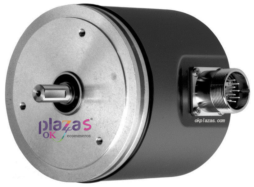
Figure 1 Encoder
Two, encoder classification
According to the working principle, encoders can be divided into two types: incremental and absolute. The incremental encoder converts the displacement into a periodic electric signal, and then converts this electric signal into a counting pulse, and the number of pulses represents the magnitude of the displacement. Each position of the absolute encoder corresponds to a certain digital code, so its indication is only related to the start and end positions of the measurement, and has nothing to do with the middle process of the measurement.
1. Incremental
Incremental encoders usually have 3 output ports, which are A-phase, B-phase, and Z-phase output. The pulse output between A-phase and B-phase is delayed by 1/4 cycle. According to the delay relationship, the forward and reverse can be distinguished. And by taking the rising and falling edges of Phase A and Phase B, the frequency can be doubled or quadrupled; Phase Z is a single-turn pulse, that is, one pulse is sent out every turn.
The grating of the incremental measurement method is composed of periodic gratings. The position information is obtained by calculating the number of increments (measurement steps) from a certain point. Since the absolute reference point must be used to determine the position value, there is also a reference point track on the rotary encoder.
2. Absolute
The absolute encoder corresponds to one circle, and each reference angle emits a unique binary value corresponding to the angle, and multiple positions can be recorded and measured through an external circle device.
When the encoder is powered on, the position value can be obtained immediately and read by the subsequent signal processing electronic circuit at any time. There is no need to move the axis to perform the reference point return operation. The absolute position information comes from a circular grating code disc, which consists of a series of absolute codes. Separate incremental track signals generate position values through subdivision, and can also generate optional incremental signals.
The absolute position value information of the single-turn encoder is repeated once every revolution. Multi-turn encoders can also distinguish the position value of each turn
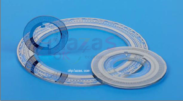
Figure 2 Disc grating of absolute rotary encoder
They have the biggest difference: In the case of incremental encoders, the position type is determined by the number of pulses calculated from the zero mark, while the position of the absolute type encoder is determined by the reading of the output code. In a circle, the reading of the output code of each position is unique, so when the power is disconnected, the absolute encoder is not separated from the actual position. If the power is turned on again, the position reading is still current and valid, unlike the incremental encoder, which must be searched for the zero mark.
Three, the working principle of the encoder
A photoelectric code disc with an axis in the center, on which there are circular and dark engraved lines, is read by photoelectric transmitting and receiving devices, and four groups of positive
The sine wave signals are combined into A, B, C, D, each sine wave has a phase difference of 90 degrees (relative to a cycle of 360 degrees), and the C and D signals are
The signal is reversed and superimposed on the A and B phases to enhance the stable signal; in addition, a Z-phase pulse is output every revolution to represent the zero reference position.
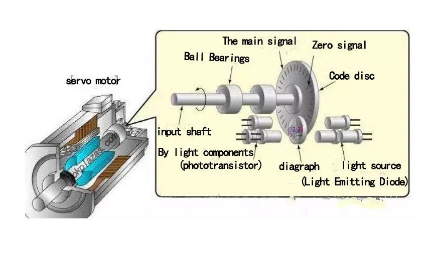
Figure 3 Encoder structure
Since the phase A and B are different by 90 degrees, you can compare whether the A phase is in front or the B phase in front to determine the forward and reverse rotation of the encoder.
Bit pulse can obtain the zero reference bit of the encoder. The materials of the encoder code disc are glass, metal, plastic, and the glass code disc is made of glass
The thin engraved lines are deposited on the top surface, which has good thermal stability and high precision. The metal code disc is directly engraved with through and impassable lines, which is not fragile, but due to the metal
With a certain thickness, the accuracy is limited, and its thermal stability is one order of magnitude worse than that of glass. Plastic code discs are economical.
The cost is low, but the accuracy, thermal stability, and life are worse.
Resolution—The number of open or dark engraved lines provided by the encoder per 360 degree rotation is called resolution, also called resolution division, or directly called how much
The line is generally 5~10000 lines per revolution.

Figure 4 Encoder
Fourth, position measurement and feedback control principle
In elevators, machine tools, material processing, motor feedback systems, and measurement and control equipment, encoders occupy an extremely important position. The encoder uses the grating and infrared light source to convert the optical signal into a TTL (HTL) electrical signal through the receiver. Through the analysis of the TTL level frequency and the number of high levels, it intuitively reflects the rotation angle and rotation position of the motor.
Since the angle and position can be accurately measured, the encoder and frequency converter can be combined into a closed-loop control system to make the control more precise. This is why elevators, machine tools, etc. can be used so accurately.
Five, summary
In summary, we know that encoders are divided into two types: incremental and absolute according to their structure. They also convert other signals, such as optical signals, into electrical signals that can be analyzed and controlled. The common elevators and machine tools in our lives are precisely based on the precise adjustment of the motor. Through the feedback closed-loop control of the electric signal, the encoder and the frequency converter can naturally realize the precise control.
-
The principle and application field of Autonics panel products (handling)
 June 12, 2021
 -
New product launch SRH1 series single-phase SSR with integrated heat sink
 June 12, 2021
 -
New product launch SRH1 series single-phase SSR with integrated heat sink
 June 12, 2021
 -
Otto protection grade IP69K new product launched Ø18mm cylindrical (SUS316L housing) photoelectric sensor BRQT series
 June 12, 2021
 -
Autonics adds shading motion mode sensor
 June 12, 2021