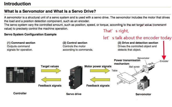
What is the principle of a rotary encoder What is the difference between an incremental encoder and an absolute encoder
What is the principle of a rotary encoder What is the difference between an incremental encoder and an absolute encoder
What is the principle of a rotary encoder What is the difference between an incremental encoder and an absolute encoder
First, I will give a conclusion. The most important difference is that the incremental encoder has no memory, and it must return to the reference zero position to find the required position after power off, while the absolute encoder has memory. Zero position, you can know where the target is.
Let’s talk about it in detail, mainly including the following:
1. What is the working principle of incremental rotary encoder?
2. What is the working principle of absolute rotary encoder?
3. What are the differences between incremental and absolute rotary encoders?
4. What is the difference between single-turn absolute and multi-turn absolute encoders?
5. What are the 3 most important factors to consider when choosing an encoder?
6.Examples of practical applications of encoders.
1.The motor butt thing
As a mechanical designer, when choosing a motor, we pay much attention to the torque and size of the motor, because this directly determines whether the motor can drag the load in the prescribed motion mode and whether it can be well arranged in a limited space.
But in the design of precision machinery, there is actually another parameter that is as important as torque and size, and that is resolution.
Speaking of resolution, many times, in the motor parameters, you can see a set of data, such as 2000Count/Turn=2000 pulses/turn, and 17bit/33bit.
Friends who know about rotating motors know that 2000C/T. This actually means that this motor has an incremental encoder. One revolution corresponds to 2000 pulses, so the resolution of the encoder is 360/ 2000=0.18 degrees.
Since relative encoders can usually do 4 times the frequency (I will explain why later), the resolution of 2000C/T can become 0.18°/4=0.045 degrees.
And 17bit/33bit is saying that this motor has a 17-bit multi-turn absolute encoder.
So the question is, what is the principle difference between an absolute encoder and an incremental encoder? What is the difference in application? Why does absolute encoder use binary to express resolution? What is the difference between single-turn and multi-turn absolute encoders?
I think, to clarify these issues, for the motor or where the rotary encoder is needed, I will not be as vague as in the past, but will be clear and straightforward to choose the appropriate encoder.
This is also my purpose of clarifying the basic concept of encoder.
2. Types, advantages and disadvantages of rotary encoders
There are usually three types of encoders on the market: Optical Encoder, Magnetic Encoder, and Capacitive Encoder.
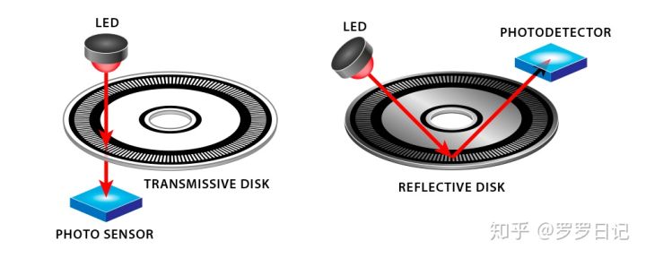
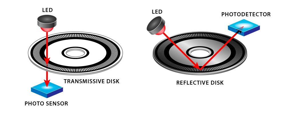
Optical encoder: In an optical encoder, the black lines block the light; the transparent window allows the light to pass through the code disc (or reflect on the code disc) to reach the sensor. When the sensor receives light, it outputs a high level, and when the light is blocked, it outputs a low level.
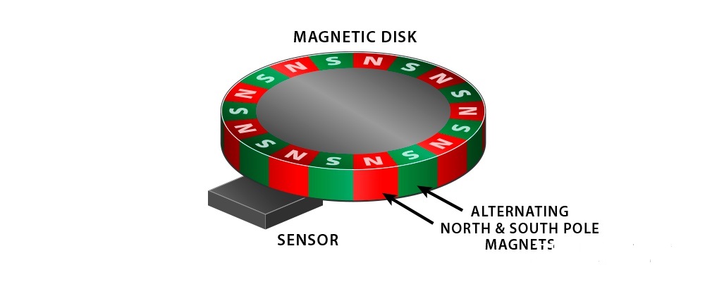
Magnetic encoder: Inside the magnetic encoder is a series of rotating magnets with alternating magnetic poles, and a sensor that detects the position of the magnetic field.
Magnetic encoders are not so susceptible to environmental influences, but due to their natural nonlinearity, magnetic encoders are not as accurate as optical encoders. They are usually used in dust, steam, vibration and other environments that may interfere with the performance of optical encoders.
At the same time, the magnetic encoder can also work in various liquid environments, and the power consumption of the magnetic encoder is less than that of the optical encoder.
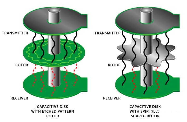
The capacitive encoder is a relatively new thing in industrial automation. This kind of encoder is as resistant to the environment as the magnetic encoder, but it cannot achieve the high resolution and accuracy of the optical encoder.
3. What is the working principle of incremental rotary encoder
To understand the difference between an incremental encoder (Incremental Encoder) and an absolute encoder (Absolute Encoder), you must first understand their working principle, right?
What is the working principle of incremental encoder?
Take the most used optical encoder as an example.
Put a picture first.
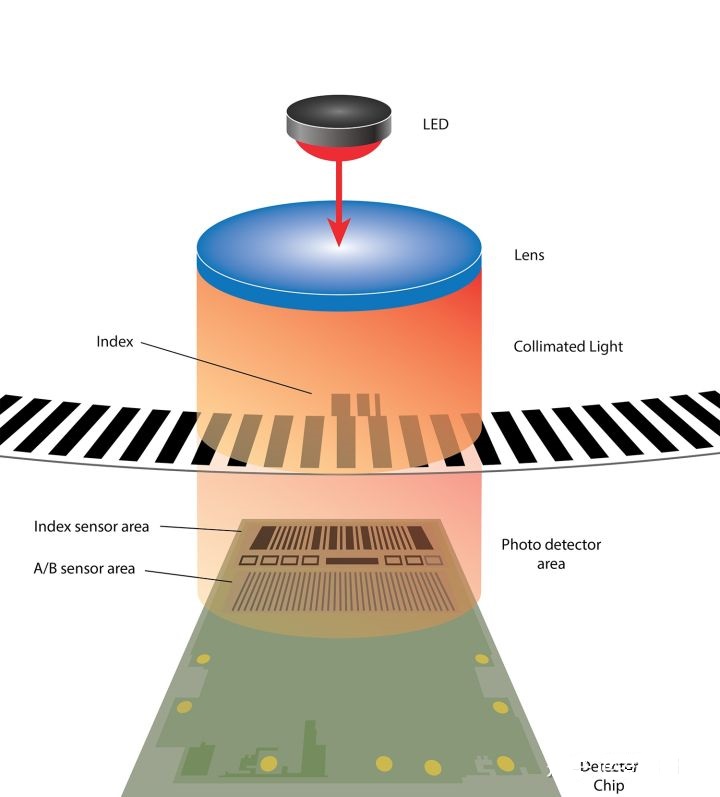
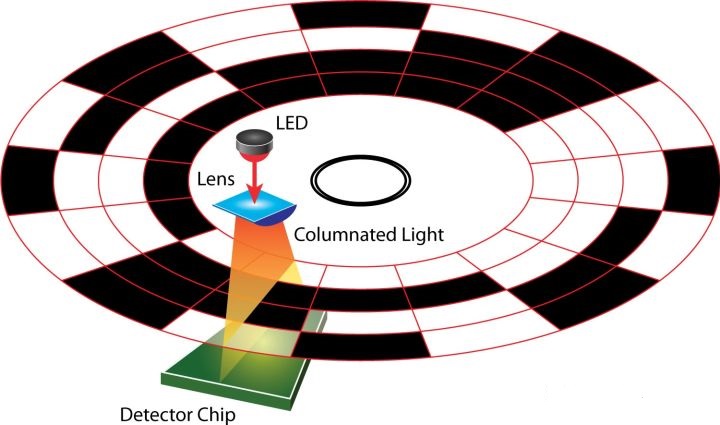
Composition of incremental optical encoder
As shown in the figure above, the system includes a code disc, an LED light source on one side of the code disc, and a photodetector chip Detector Chip on the other side.
There are a series of black markings and transparent windows on the code wheel. The black markings are opaque but the windows are transparent.
After the LED light passes through the lens (Lens), it forms parallel light and hits the code disc. The light is blocked at the black scribe line, and passes through the code disc at the transparent window to illuminate the sensing area of the sensor below.
There are two areas on the sensor that can sense signals, one is the Index Sensor Area, which is the initial zero sensing area, and the other is the position signal change sensing area A/B Sensor Area.
The zero position sensor is also called Home, in some places it is also called Zero, and the signal generated by its detection is called Z signal.
Not all incremental encoders have a reference mark. For example, some applications on conveyor belts don’t need it, and some incremental encoders have more than one reference mark. I don’t want to discuss it here. Find out for yourself.
The LED light passes through the code wheel window and transmits to the sensing area of the sensor on the other side. When the code wheel rotates, the fixed sensor can read this alternating pattern of light, and then report the position information back to the mechanical system.
The waveform generated by the sensor is as shown in the figure below. It is a repetitive square wave (some encoders transmit sine waves or cosine waves), and the high level and low level occupy the same time because of the opaque grating and transparent window interval on the code disc. At the same angle, a black line and a transparent fan area constitute a cycle, corresponding to a low level and a high level in the waveform diagram, which is a 360-degree electrical cycle.
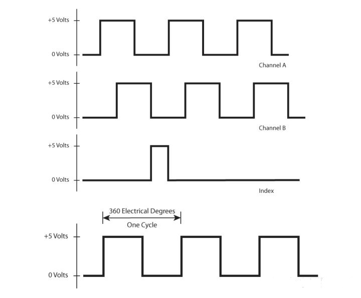
Incremental encoder waveform
Why are there two channels in the waveform graph, one A and one B? What is it used for?
Careful, you may have discovered from the picture just above that A/B Sensor Area is the cause of the two channel signals.
How to explain, let's take a detailed picture.
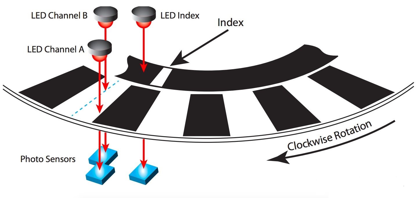
Incremental encoder principle detailed diagram
As can be seen from the above picture, the photoelectric sensor A and the sensor B are not in the same radial direction, but have an angular misalignment. How much is the misalignment? It happens to be half of the angle occupied by a scribe line, which is 1/ 4 physical cycles.
We know that if there is only one sensor A, then when the zero position is triggered, the sensor A will start counting. After passing a black line and a transparent line, the waveform will form a low level and a high level, which is a Period, but it does not know the direction of rotation of the code wheel, which may be counterclockwise or clockwise.
Therefore, the purpose of adding sensor B is obvious: cooperate with sensor A to determine the rotation direction of the code wheel.
Because A and B are misaligned by 1/4 of the physical period, (that is, the electrical pulse period is 90 degrees apart, so it is also called quadrature pulse. The English is Quadrature, and the A-Quad-B we often hear comes from here), so The light will successively pass through the transparent window and hit the sensors A and B, forming a 1/4 period difference.
For example, if you rotate clockwise, A leads B by a quarter of a period, then rotate counterclockwise, and A must lag B by a quarter of a period. Therefore, the direction of rotation can be judged according to whether A is leading or lagging B.
OK, at this point, we understand the working principle of the incremental encoder: find the zero position through Index, calculate the rotation angle through the number of pulses, determine the rotation direction through the relative hysteresis of the AB channel, and use the time occupied by the waveform, or the wave The pulse frequency is used to judge the speed.
Think about it again. The AB channel is 1/4 cycle apart. What else can it be used for?
As you may have guessed, it is the 4 times (multiplier) resolution that I mentioned at the beginning.
How to achieve it?
Look at the waveform diagram.
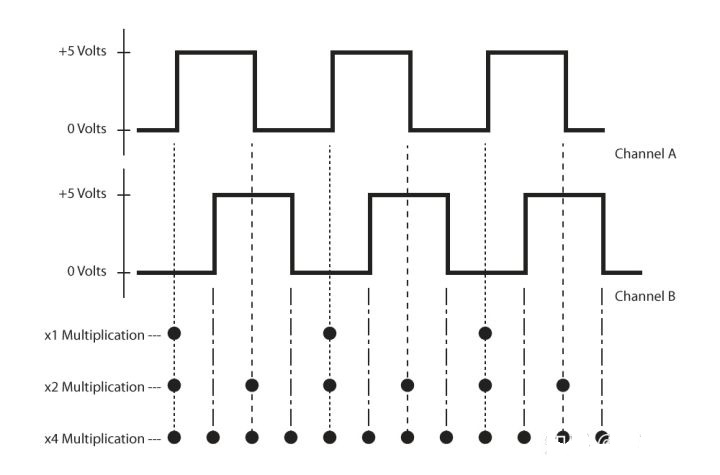
Incremental encoder frequency multiplication method
Here, take 100 physical cycles per circle as an example.
Double X1: When the code wheel rotates, if we calculate each rising edge of channel A pulse (from 0 to 5V), then 100 pulses will be obtained per revolution.
2 times X2: When the code wheel is rotating, if we calculate each rising edge and each falling edge of channel A (from 5V to 0), then 2 pulses will be obtained per cycle, and a total of 200 pulses per revolution.
4 times X4: If we calculate each rising and falling edge of channel A and channel B, each physical cycle will get 4 pulses, totaling 400 pulses per revolution.
Because the physical reticle of an incremental encoder is at the same angle apart, in essence, it calculates the rotation angle by counting the number of pulses.
In the same circle, the number of pulses per circle obtained by different frequency multiplication methods is different. Obviously, the resolution obtained by frequency multiplication is the highest.
This is the principle of 4 times the resolution.
Therefore, the resolution of 2000C/T can be changed to 0.18°/4=0.045°.
But it should be understood that this 4-fold multiplication does not change the angle between the physical markings of the code disc, but only the change in the number of electrical pulses, and this multiplication is usually done in the controller or counter. The signal quality Good and reliable.
What if I want to obtain a higher resolution without changing the code wheel?
You can use Interpolation, which is signal interpolation.
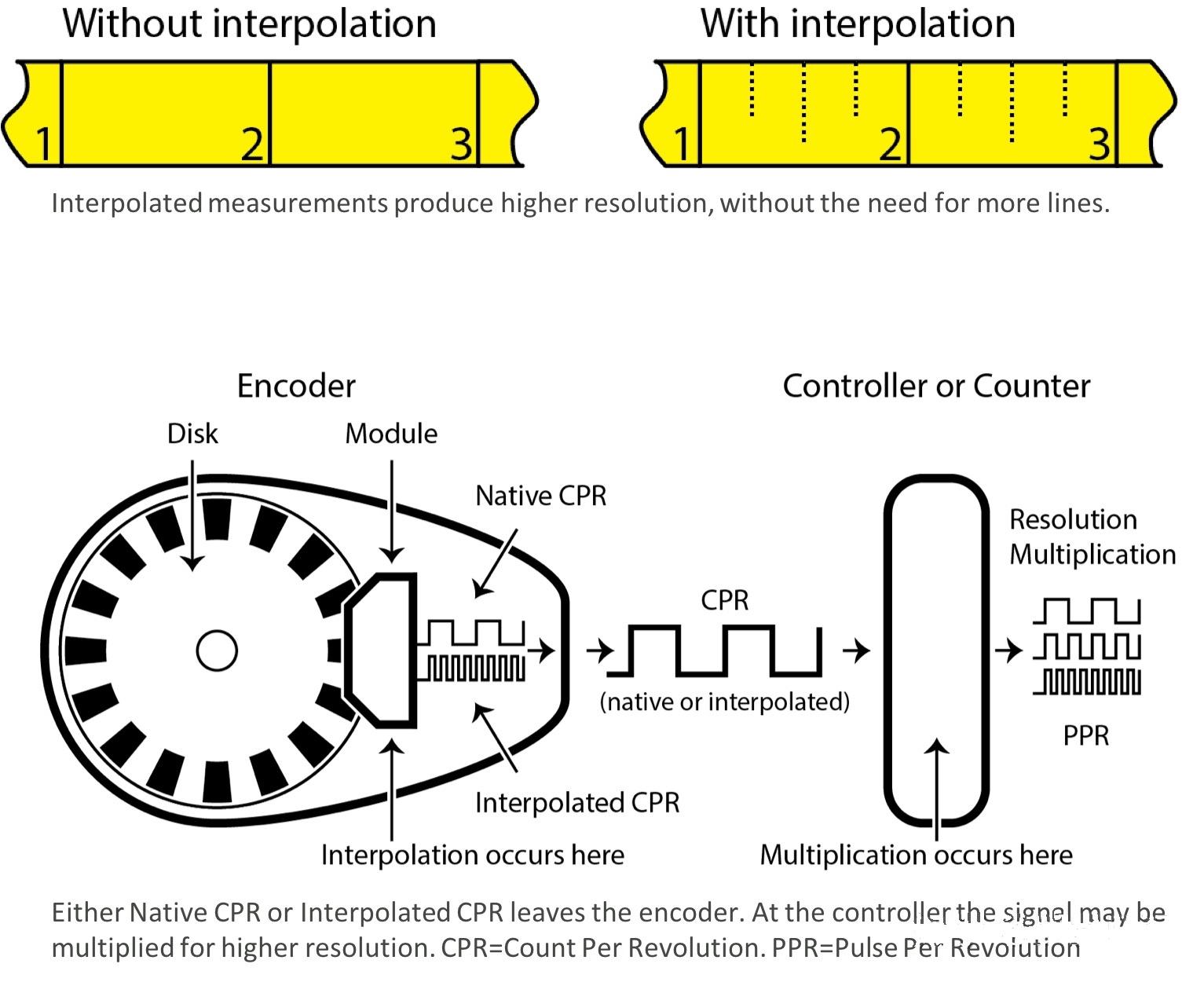
Interpolation diagram
What is the meaning of interpolation? I don't understand much, but mathematically speaking, interpolation is to predict unknown data through known data.
In the encoder application, because the actual position may be located between the black engraved line and the transparent window, interpolation can obtain the value of these positions, thereby obtaining a higher resolution.
In theory, interpolation can achieve unlimited resolution, but too high interpolation will also introduce new problems, such as the signal is susceptible to electrical noise and thus reduce the accuracy, requires matching drivers and controllers, and a lot of data processing Need to spend more time, need faster response, etc.
At present, in the product catalog of a certain supplier, I see that the highest interpolation multiple is 20000 times, and the resolution reaches 0.002arcsec. Of course, this code wheel is also very large, with an outer diameter of 206mm, and the physical period of a circle is 32400 (that is, 32400 Line Count).
The physical resolution of this code wheel is: 360/32400=0.01111°, the resolution after interpolation is: 0.01111/20000*3600=0.002arcsec, where division by 3600 is the unit conversion. The accuracy that this encoder can achieve after installation is ±1arcsec=±1/3600°.
4. What is the working principle of an absolute rotary encoder?
The working principle of an absolute encoder is different from that of an incremental encoder.
How is it different?
The pie-sharing game has begun.
Let's look at a picture first.
The principle of absolute rotary encoder
This figure is a schematic diagram of a 16-bit absolute encoder. The entire circle is divided into 16 parts, that is, there are 16 sectors.
It is similar to the picture of an incremental encoder, but there is one difference: in the radial direction, each sector is divided into 4 parts.
The LED light is irradiated from one side of the code disc. Correspondingly, there is a detection chip on the other side of the code disc. The detection chip has 4 sensing areas. Each sensing area can obtain the status of each copy of the same sector.
In the transparent window, the light passes through, and the sensing area senses the signal. In the opaque area, the light cannot pass through and the sensing area cannot sense.
If the sensing and non-sensing are regarded as two states, represented by 1 and 0 respectively, then each sensing area can represent two states.
Furthermore, these 4 copies (4 bits) in the same sector can represent 2^4=16 states. This is why the code wheel is divided into 16 copies in the circumferential direction, which is actually equivalent to performing each position Code, each code corresponds to a specific location.
You may also want to ask if you can divide it into 4 in the radial direction and a few more in the circumferential direction. There is no point in multi-pointing, because there are only 4 digits in the radial direction, which cannot represent more positions. Less points can not make full use of the total number of states sensed, so it is just right to divide 2^4=16.
For example, in the picture below, from left to right, 0001, 0101, and 1100 can be represented respectively, and the decimal system is the 1, 5, and 12 positions.

Absolute encoder coding method
0101 is converted to decimal: 0*2^3+1*2^2+0*2^1+1*2^0=5. 1100 is converted to decimal: 1*2^3+1*2^ 2+0*2^1+0*2^0=12.
At this point, we basically understand the principle of absolute encoder: for each position, given a unique code, and then use the sensor to identify the code of each position, and output the corresponding unique signal to indicate Specific location.
If you want to get a higher resolution, you need more code bits, that is, you need to engrave more specific codes in the circumferential direction (this usually increases the code disk).
For example, if 17 bits are required, that is, 2^17=131072 positions, then 131072 different codes are needed, and the resolution at this time is 360/131072=0.275°.
Of course, not every manufacturer's coding method is the same as the above example. Some manufacturers do not divide in the radial direction, only in the circumferential direction, but the basic idea is the same, that is, a unique code is used to indicate a unique position.
This is the core idea of the absolute encoder.
I just finished talking about the encoding method, so what is the difference between the output waveform of an absolute encoder and an incremental one?
Take the optical absolute encoder as an example. The output waveform of a typical absolute encoder is as follows.
What is used here is pulse width modulation (PWM=Pulse Width Modulation).
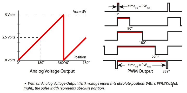
Absolute encoder waveform
A 10-bit absolute encoder can output 2^10=1024 unique codes. How to represent each specific position in the figure?
Expressed by pulse width.
For example, the starting zero position is represented by a minimum pulse width of 1 microsecond. At 180°, it is represented by a pulse bandwidth of 512 microseconds.
Similarly, for other positions, different pulse widths are used. As the code wheel rotates, longer and longer pulse bandwidths are transmitted.
By the way, on the left side of the figure above is a waveform diagram of an absolute magnetic encoder, which uses the voltage level to indicate different positions.
These waveform information, according to the configuration of the control system, can be transmitted to the controller through different communication interfaces for feedback control.
5. What is the difference between absolute single-turn and multi-turn encoders?
Absolute encoders are divided into single-turn and multi-turn, namely Single-Turn Absolute Encoder and Multi-Turn Absolute Encoder.
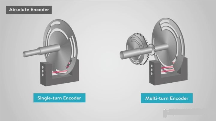
Schematic diagram of single-turn and multi-turn absolute encoders
A single lap is easy to understand. Just like the minute hand in a clock, it keeps turning one circle after another. After 60 minutes, the watch resets and does not record the number of rotations. In this case, it is not known how many hours.
Multi-turn, like a clock with a minute hand and an hour hand. At any time, the minutes and hours can be read.
So a multi-turn encoder can record many many turns.
In the actual multi-turn encoder, three methods are commonly used to realize the number of turns recording.
The first, like the picture above, uses mechanical gears to couple multiple shafts inside the encoder to calculate the total number of turns. This method, because mechanical gears are used, will cause wear and tear, making The accuracy is reduced, and the mechanical gear will take up a lot of space, so the encoder size is too large.
The second is to use an electronic counter and capacitor to count the total number of turns, but the cost is that a battery needs to be installed inside the encoder and the battery needs to be checked regularly.
The third type is that in some magnetic encoders, Wiegand wire is used and the Wiegand effect is used to count (Wiegand effect). This kind of encoder does not have too many mechanical structural parts and can be made very small.
The Wiegand effect is also what I learned when I was learning about the encoder, so I will explain a little bit more.
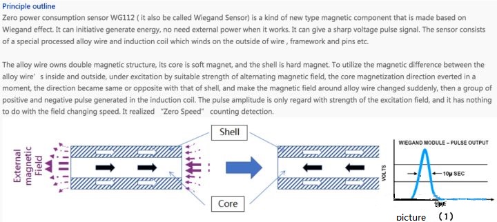
Wiegand effect
Wiegand gold wire, which is made of a special alloy, has a hard magnetic (permanent magnet, not easy to demagnetize) metal shell and a soft magnetic (easy to demagnetize and magnetize) metal core. The Wiegand line exhibits two apparently discontinuous hysteresis curves, which is called the Wiegand effect.
Under the action of appropriate magnetic field strength, the Wiegand wire core magnetic field will reverse, and its magnetic field is the same as or opposite to the outer hard layer, so that a nearby coil generates a pulse. The size and shape of the pulse is the same as the speed of the external magnetic field. It doesn't matter, the magnetic encoder uses this pulse to record the number of revolutions and write the data into a stable memory.
Of course, a single-turn encoder can also calculate the number of revolutions by the number of signal repetitions, but it is not as straightforward as a multi-turn encoder.
For a single-turn encoder, if it has turned more than one turn, after the power is turned off and restarted, it is not known how many turns have been turned, that is, the absolute position is not known.
This feature determines that the single-turn absolute encoder is only suitable for applications where the absolute position is required for startup, but during operation, the rotation is less than one full circle.
The multi-turn encoder has a physical absolute position record of the number of turns, so the multi-turn can obtain a longer and farther absolute position than a single turn.
But at the same time, a new problem has arisen about multi-turn encoders.
What happens if the number of rotations exceeds its total recording capacity?
At this time, the number of laps will overflow, or re-count, or the drive and controller provide a special position tracking called "modulus positioning", which can store any overflow movement, that is, the part of the rotation that exceeds the recorded lap, and Use this information to provide accurate positioning.
At this point, we have re-understood the difference between single-turn and multi-turn encoders: a single-turn can only record movement within one turn, and a multi-turn can record long rotation or linear displacement.
All right.
Now let's go back and take a look at the 17bit/33bit mentioned at the beginning of the article.
What does this mean? I believe you have understood from the above explanation.
The meaning of 17bit/33bit is: 17bit means that there are 2^17=131072 pulses per revolution, and 33bit means that the total number of pulses is 2^33=2^17*2^16, then this multi-turn encoder Can record 33-17=16bit=2^16=65536 circles.
Note that when calculating the resolution here, its resolution is only related to the number of pulses in one revolution, and has nothing to do with the total number of revolutions, that is to say, the resolution of this encoder is 360/131072=0.00275 degrees.
If a motor uses this encoder, the ball screw is driven by this motor, and it moves forward 5 mm in a circle, then the theoretical resolution is: 5mm/131072cnt=0.038um/cnt.
Of course, the actual resolution must be lower than this. After all, the ball screw system also has clearance, and most of the time, the clearance of the mechanical system is the shortcoming of the entire system.
7.What is the difference between an incremental encode
-
The principle and application field of Autonics panel products (handling)
 June 12, 2021
 -
New product launch SRH1 series single-phase SSR with integrated heat sink
 June 12, 2021
 -
New product launch SRH1 series single-phase SSR with integrated heat sink
 June 12, 2021
 -
Otto protection grade IP69K new product launched Ø18mm cylindrical (SUS316L housing) photoelectric sensor BRQT series
 June 12, 2021
 -
Autonics adds shading motion mode sensor
 June 12, 2021