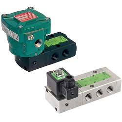
How to choose the structure material of solenoid valve
How to choose the structure material of solenoid valve
Because solenoid valves are used to handle various fluids, from clean dry air to corrosive chemicals, the temperature range is approximately from zero to 1,000 degrees Celsius, and the pressure ranges from close to full vacuum to 50,000 psig. ) Or greater. There are many materials available for electromagnetic valves, but some places require imported alloys and metals, which can resist fluid corrosion. However, because most valves are used in an environment with no corrosion, pressure and temperature. Cast iron and carbon steel are the most commonly used valve body materials.
Most electromagnetic valve materials can be divided into two categories:
Various types of pressure parts for solenoid valve body, upper valve cover, lower valve dust and connecting bolts.
Trim materials for valve cores, seat rings, sleeves, valve stems, guide rail bushings and filling parts of solenoid valves. The materials used for the various pressure parts used in the pressure parts are mainly selected according to the following characteristics of the fluid medium: pressure, temperature, corrosion and wear characteristics. In the selection of materials, sometimes a compromise must be adopted. For example, a good wear-resistant material may not be satisfactory. This is because when dealing with some special fluids, their anti-corrosion performance is not good.
Because the electric single-seat control valve used on site is in direct contact with the medium to be adjusted, the working environment is very harsh and various failures are prone to occur. In addition to troubleshooting these faults at any time, during the production process, frequent maintenance and regular overhauls are also required. Especially for regulators that are used in a particularly harsh environment, more attention should be paid to maintenance and regular inspections. Different forms of single-seat electric control valves have different faults and causes.
Fault 1: The actuator does not act, but the power supply and signal lights of the control module are on. Solution: Check whether the power supply voltage is correct, whether the motor is disconnected, whether there is a disconnection from the ten-pin plug terminal to each line terminal, whether the wiring plugs of the motor, potentiometer, and capacitor are intact, and judge whether the control module is intact through comparison and transformation.
Fault 2: The actuator does not move, neither the power light nor the signal light. Processing method: Check whether the input signal polarity is correct, and judge whether the control module is intact by comparison and interchange method.
Fault 3: The actuator shocks and screams. Treatment method: Mainly due to the sensitivity adjustment is too high, the insensitivity area is too small, and the allergy is poor, which causes the small circuit of the actuator to be unstable and produce oscillation. The sensitivity potentiometer can be fine-tuned counterclockwise to reduce the sensitivity; the hydraulic pressure is too large to make the actuator thrust insufficient ; The control valve has a larger choice and often works at a small opening.
Fault 4: The actuator does not act normally, but the motor does not stop after the limit switch acts. Solution: Check whether the limit switch and the wiring of the limit switch are faulty, and judge whether to replace the control module.
Fault 5: The drive belt is broken. Solution: Check whether the internal transmission part of the actuator is damaged, whether the stuck potentiometer is adjusted correctly, and whether the limit switch is adjusted correctly.
Fault 6: Improper adjustment of system parameters, causing frequent oscillation of the actuator. Solution: Improper adjustment of the parameters of the regulator will cause the system to produce varying degrees of vibration. For single-loop regulation systems, if the proportional band is too small, the integral time is too short, and the differential time and differential gain are too large, which will cause the system to oscillate. By adopting the method of system tuning, the parameters can be selected reasonably and the circuit can maintain a stable operating speed.
Fault 7: The actuator motor heats up quickly, oscillates and crawls, and stops for a short time. Solution: Use 2V AC voltage at the input of the control module to test whether the AC interference is affected; check whether the signal line is isolated from the power line; whether the wiring between the potentiometer and the potentiometer is good; whether the feedback element is operating normally.
-
The principle and application field of Autonics panel products (handling)
 June 12, 2021
 -
New product launch SRH1 series single-phase SSR with integrated heat sink
 June 12, 2021
 -
New product launch SRH1 series single-phase SSR with integrated heat sink
 June 12, 2021
 -
Otto protection grade IP69K new product launched Ø18mm cylindrical (SUS316L housing) photoelectric sensor BRQT series
 June 12, 2021
 -
Autonics adds shading motion mode sensor
 June 12, 2021