How to understand the given source and control signal source of SEW inverter?
How to understand the given source and control signal source of SEW inverter?
How to understand the given source and control signal source of SEW inverter?
Inverter (Inverter) is the main equipment of modern AC speed regulation, and its control object is a three-phase (or single-phase) AC asynchronous motor. We know that the speed formula of a three-phase asynchronous motor is:
n=60f/p(1-s). “N” represents the speed of the motor; “f” represents the frequency of the alternating current; “p” represents the number of pole pairs of the motor; “s” represents the slip rate (the difference between the speed n of the asynchronous motor and the speed n0 of the synchronous magnetic field The ratio of the speed of the magnetic field n0). For a finished motor, the number of pole pairs p is constant, so we can only change the speed of the motor by changing the frequency of the alternating current, which is also the speed regulation principle of the inverter.
Skilled use of inverters is not a simple matter. Brands of inverters on the market now
There are many differences in the ways of using products of major brands. But some places are connected. For example, you need to configure the motor parameter of the motor, you need to configure the control (control source), and you need to configure the setpoint. I was once asked at the scene: why the inverter There is a given source (setpoint source) and a control signal source (control signal source) in the parameters. What do they mean? Today in this article, we will take SEW's MDX61B as an example to explain this problem
The frequency converter is used to change the speed of the motor. By setting different speed values, the motor can run at different speeds. This kind of speed setting value is usually called the inverter's "speed setpoint value", or "setpoint" for short. For example, if the motor is expected to run at a speed of 700 revolutions per minute, "700 revolutions per minute" here is called "speed reference".
In addition to "speed reference", "frequency reference" can also be set. Because the frequency of the current is proportional to the speed of the motor, the speed of the motor can be reduced by reducing the frequency of the current.
Whether it is "speed setting" or "frequency setting", it can be referred to as "setting" for short. The signal source of a given value is called "setpoint source". SEW's MDX61B inverter
The P100 parameter is used to configure the setpoint source of the inverter, as shown in the figure below:
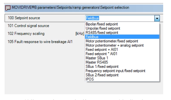
It can be seen that this inverter supports many kinds of given sources, which can be communicated
(RS485, Fieldbus, SBus, etc.) to set the setpoint, you can set the constant setpoint by analog or terminal (Bipolar/fixed setpoint, Unipolar/fixed setpoint, Fixed setpoint+AI01, Fixed setpoint x AI01, etc.), You can also set the constant to the frequency input (Frequency setpoint input/fixes setpoint)set.
Let's give two examples:
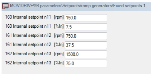
1)When [Bipolar/fixed setpoint] is selected, the setpoint of the inverter can be obtained through the input of analog AI1/AI2. The given value is positive to make the motor run clockwise, and the given value is negative to make the motor run counterclockwise. In addition to analog, you can also set a fixed speed value in parameter P16x, and then control it through the external terminal (X13) (see the following [terminal control] for details).
2) Frequency setting (Frequency setpoint input/fixed setpoint). When the reference source is set to [Frequency Reference], the inverter will detect the input frequency of digital input DI04, and control the motor speed through this frequency value. At this time, the parameters of DI04 must be set to [no function], and DIP switch S14 must be set to [ON]. In the process of adjusting the speed of the inverter, in addition to setting the operating speed (or operating frequency) of the inverter,
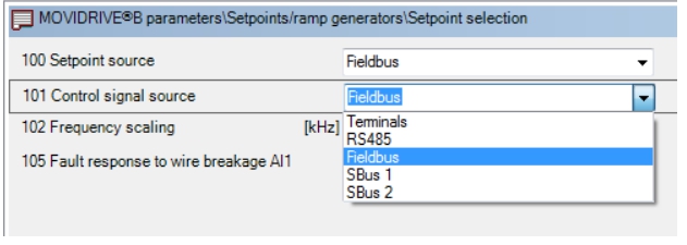
Some other signals are needed, such as: when to start? When will it stop? Does the motor rotate forward or reverse? These signals are collectively referred to as the "control signal" of the motor. The source of the control signal, called "control signal source" MDX61B supports four control signal sources: Terminals, RS485, Fieldbus, SBus1 and SBus2, as shown in the figure below:
Digital input terminal [X13] used for terminal control. The following picture is the terminal definition diagram of X13:
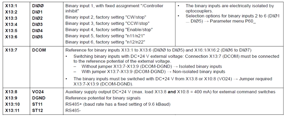
As can be seen from the figure, the factory default setting of X13:2 (DI01) is "CW/stop", that is, "forward/stop"; the factory default setting of X13:3 (DI02) is "CCW/stop", that is "Reverse/Stop"; the factory default setting of X13:4 (DI03) is "Enable/stop", that is, "enable/stop"; the factory default setting of X13:5 (DI04) is "n11/n21"; X13 : The factory default setting of 6 (DI05) is "n12/n22";
Note: CW is the abbreviation of Clockwise, which means "clockwise", which is the "forward rotation" mentioned above; CCW is the abbreviation of Counterclockwise, which means "counterclockwise", that is, "reverse"; when we put P101 When the value of is set to [Terminals], if the input signal of X13:2 terminal is 1, the motor will rotate forward; if the input signal of X13:3 is 1, the motor will reverse; of course, before the motor rotates, first To [enable], which is the X13:5 terminal
The input signal is 1; when the input signal of X13:6 is 1, the motor runs at the speed set in the "n11/n12" parameter; when the input signal of X13:7 is 1, the motor runs at the "n21/n22" parameter Run at the set speed;
This way of controlling the start, stop, forward and reverse rotation of the motor by controlling the input signals of certain terminals of the inverter is called the terminal control of the inverter, and the terminal is a control signal source.
The terminal control of the inverter is the most basic control method and the factory default control method. However, this method needs to occupy the output point of the PLC and increase the workload of the wiring, so it is generally recommended to use the communication method for control. MDX61B supports RS485, FieldBus and SBus communication methods for control, adopts the agreed process data format (Process Data), and controls the inverter through the control bit (bit) of the control word (Control Word). There are many knowledge points covered by communication methods, and we will discuss them slowly later.
The summary of this article is as follows: The given source of MDX61B inverter and the control signal source are separated, and the speed can be given by means of Fieldbus, and the start and stop can be controlled by means of terminals; or by means of frequency. The setting is carried out, and the control is carried out through the fieldbus; of course, other combinations are also possible, for example, both the setting source and the control signal source use Fieldbus. Okay, let’s talk about it today
-
The principle and application field of Autonics panel products (handling)
 June 12, 2021
 -
New product launch SRH1 series single-phase SSR with integrated heat sink
 June 12, 2021
 -
New product launch SRH1 series single-phase SSR with integrated heat sink
 June 12, 2021
 -
Otto protection grade IP69K new product launched Ø18mm cylindrical (SUS316L housing) photoelectric sensor BRQT series
 June 12, 2021
 -
Autonics adds shading motion mode sensor
 June 12, 2021