How to use the diagnostic functions of the Festo bus node CPXFB33
How to use the diagnostic functions of the Festo bus node CPXFB33
How to use the diagnostic functions of the Festo bus node CPXFB33
A good bus module not only needs to be able to provide stable and reliable functions, but also needs to be able to quickly and easily inform the cause of the failure when the system fails. This is the diagnostic function often referred to. In the previous article, we introduced Festo's CPX electrical terminal Profinet bus node module FB33 (see: How to use the CPX electrical terminal Profinet bus node module-FB33), today’s article, let’s take a look Look at the diagnostic function of FB33.
FB33 supports multiple diagnosis functions, including LED diagnosis, status bit diagnosis, IO interface diagnosis
(STI) and Profinet online diagnosis, etc. Regarding the diagnostic function of the LED light, we have already introduced it in the previous article. In today's article, we mainly discuss the status bit diagnostic function.
Two conditions are required to enable status bit diagnosis: First, use the DIL switch (DIL) of the bus module to activate the status bit diagnosis function; secondly, perform the corresponding hardware configuration in the hardware configuration of Step7.
Let’s review the appearance of FB33 first:
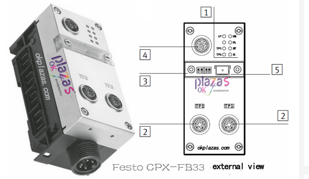
The position indicated by "3" in the figure is the dial switch (DIL) of FB33, which is composed of two sets of dials (two dials in each group, 4 in total). The following picture will look clearer:
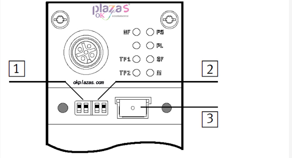
In the above figure, 1 and 2 are two sets of DIP switches, the numbers from left to right are 1.1, 1.2, 2.1 and 2.2. The first group (1.1 and 1.2) is used to set the operating mode of the bus node; the second group (2.1 and 2.2) is used to set the diagnostic mode (in Remote IO mode). Turn the switch to the top to indicate ON (ON), and to the bottom to indicate OFF.
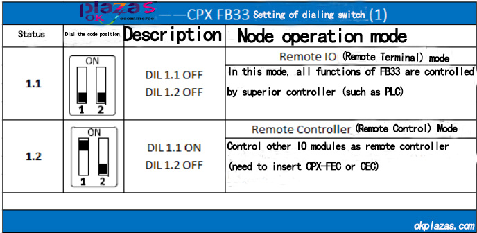
The first group of DIP switches is used to set the operating mode of the bus node. CPX-FB33 supports two operating modes: remote terminal (Remote IO) mode and remote controller (Remote Controller) mode, the setting method is as follows:
The second group of DIP switches is used to set the diagnostic mode of the module. CPX-FB33 supports four modes: diagnosis closed, status bit diagnosis, IO interface diagnosis (STI) and reserved function. The specific setting method is as follows:
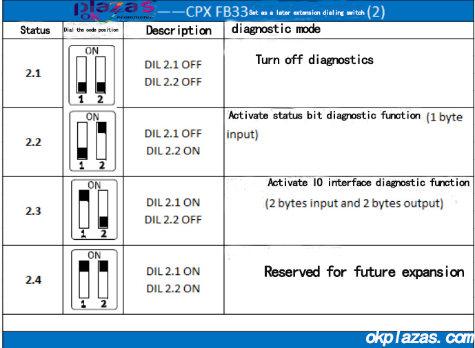
To activate the status bit diagnosis function, the DIP switch should select the status 1.1 and status of the above two tables
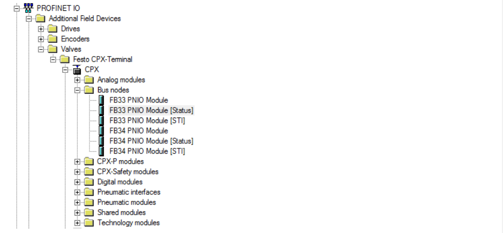
2.2. After the DIP switch on the hardware is set, the correct hardware configuration needs to be selected in the hardware configuration of Step7. FB33 has three hardware modes. To use the status bit diagnosis function, you need to select "FB33PNIO Module[Status]", as shown below:
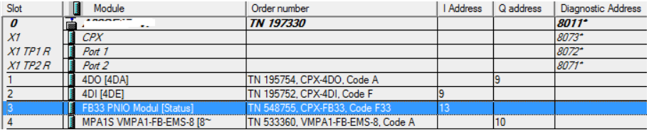
The input address (Iaddress) of the configured FB33 is the address of the diagnostic byte, as shown in the figure below:
The error information expressed by the 8 bits of the diagnostic byte is as follows:
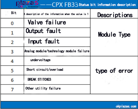
When the bus node has no error, the value of the diagnostic byte is 0 (bit0~bit7 are all 0). Ok, let's talk about the status bit diagnosis of FB33 first.
-
The principle and application field of Autonics panel products (handling)
 June 12, 2021
 -
New product launch SRH1 series single-phase SSR with integrated heat sink
 June 12, 2021
 -
New product launch SRH1 series single-phase SSR with integrated heat sink
 June 12, 2021
 -
Otto protection grade IP69K new product launched Ø18mm cylindrical (SUS316L housing) photoelectric sensor BRQT series
 June 12, 2021
 -
Autonics adds shading motion mode sensor
 June 12, 2021