Optimize the installation method of rotary encoder
Optimize the installation method of rotary encoder
Encoder is a small component in a complex system. It can help manufacturers produce high-quality parts or move objects from point A to point B quickly and smoothly. If you decompose the system, its main components include a motor, a driver or amplifier, and possibly a brake and an encoder. When installing, the encoder is the most troublesome. This article will introduce different encoder installation methods and their advantages and disadvantages from the perspective of space, surrounding environment and mechanical factors, and will also introduce the consequences of incorrect installation.
1 Introduction
The encoder is a component in the motion control system, used to feed back signals to the drive for precise speed and position control. Encoder selection seems to be a tricky thing. Mainstream encoder manufacturers are constantly releasing new encoder series, making the product line increasingly large, and the options for the same series of products are also increasing.
Although the interface and electrical options of each encoder series may seem complicated, the choice is still yours. When you select a driver, the driver parameters will contain appropriate input options, and the encoder must be selected based on these options. The installation method is the most important point of the uneven encoder. A reasonable choice of installation method can improve the life and performance of the encoder at the same time. If you want to do well, you must first sharpen your tools, and the appropriate installation options are just like the appropriate "tools."
2.Coupling
2.1 Coupling definition
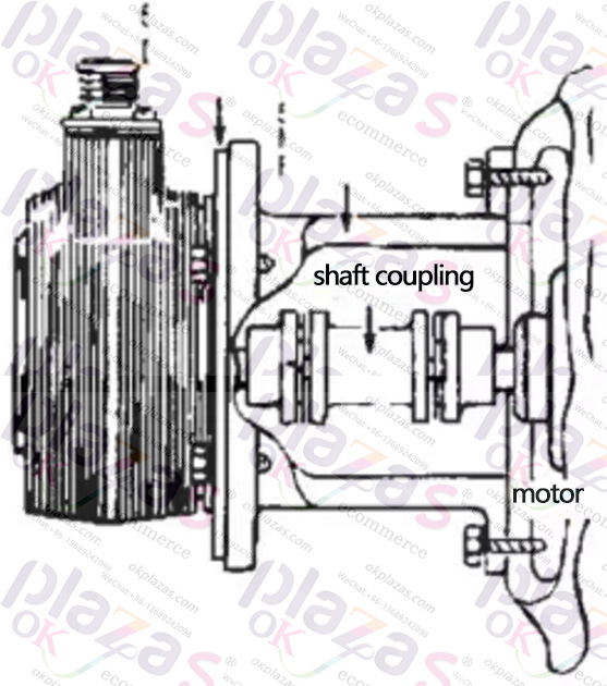
If flange or foot-mounted encoder is selected, the encoder can be installed on the motor by using 1 coupling and 1 adapter. The coupling is fixed to each shaft by a set screw, and is equipped with a spring or mechanical device to eliminate the impact, vibration or deviation from the motor shaft. This connection method is common when the encoder is paired with an old, non-standard motor, and the encoder does not have an O-ring type or a hollow shaft type so that it is difficult to compensate for the excessive movement of the motor shaft.
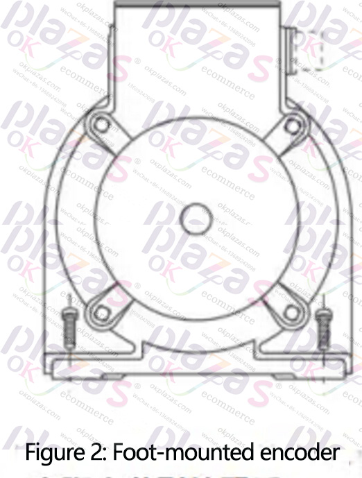
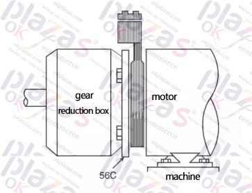
The foot installation is also to install the encoder directly on the motor shaft or drive through a belt. The reason for choosing this method is the same as the choice of flange installation. However, the encoder body is not directly or indirectly installed on the surface of the motor under this installation method, but installed horizontally like the motor. Foot-mounted encoders generally also have a Nema56C surface, which is used to mount a gear set or another ring encoder on the surface.
2.2 Benefits of coupling
Using couplings to isolate the encoder has many benefits. This type of installation can usually be electrically isolated from the motor. When there is no electrical isolation, the encoder is easily affected by the power supply from the motor and the induced current generated by the motor. If there is electrical noise, the encoder output may lose pulses, increase pulses, and even damage the encoder. Mechanical isolation is another benefit. The elastic coupling can absorb the shaft end offset, and the encoder can be installed in an old motor or a motor that works under high shock and vibration conditions.
2.3 Precautions for coupling
The disadvantages of using couplings are mainly mechanical. The primary disadvantage of using couplings is that they increase the length of the shaft. Taking into account the gap between the bracket, the shaft and the coupling, and the encoder housing, the length of the motor shaft will increase by a total of about 7 inches after the coupling is installed. In addition, installing the coupling also requires several steps (ie: shaft alignment and tightening connection).
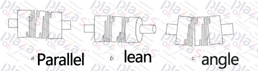
When installing the coupling, any form of misalignment error in Figure 3 will bring undesirable consequences that we do not want to see. Most importantly, the coupling is exposed to stresses that could have been avoided. These stresses will eventually cause the coupling material to tear or damage.
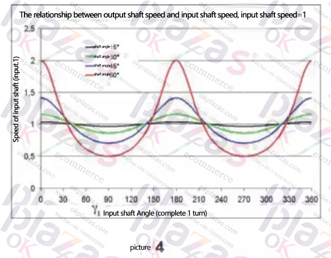
Finally, misalignment errors may affect the speed feedback. This effect is similar to the output speed of a shaft driven by a universal joint, as shown in Figure 4. Speed fluctuations may cause drive failure or product damage due to excessive vibration.
3. The spring leaf is directly connected to the installation
3.1 Definition
The encoder is directly mounted on the motor shaft through a spring leaf. The encoder has its own bearing, so no mechanical alignment is required. This kind of encoder also has rod-type or plate-type springs, which can be fixed on the surface of the motor or other fixed parts by screws to keep the encoder body from rotating. Motors are driven by different power sources, and different power sources will generate different types of currents at the shaft and bearings. In order to protect the encoder and motor bearings, a plastic bushing is usually used to isolate the direct-connected encoder shaft between the motor and the encoder shaft. Encoders without plastic bushings or inserts need to be grounded through the motor shaft or other shaft grounding kit.
3.2 Advantages of Directly Connected Encoder
Using the direct connection scheme, it is easier to install the encoder on the motor shaft reasonably. When adopting the ring type installation method, accurate size information of the motor surface is required. Slotted springs can even be installed on shafts with varying radius. There is no need to align the sensor axis during installation. This means that as long as the shaft sleeve is tightened, the installation on the shaft is complete. There are plastic bushings or plastic fasteners in the encoder, which can extend the life of the bearing, thereby saving the cost of the motor and the encoder. The spring plate can absorb the impact of sudden movement of the motor shaft. This is another design that can extend the life of encoder bearings.
3.2 Precautions for direct installation
Direct-connected encoders usually have a large moving axis in the housing. This means that the contact area of the internal circuit of the encoder is larger than that of the coupling-connected encoder. The ring encoder (section 4) has no contact on the entire shaft. Encoder manufacturers are constantly adopting new methods to improve this problem. One method is to use a labyrinth seal.
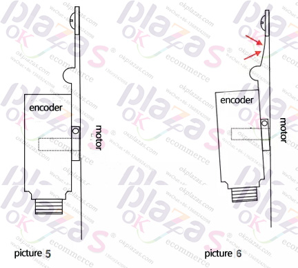
It is recommended to use both hands or a balance clamp to slide the encoder on the shaft. In order to extend the service life of the spring, the encoder should also be installed in the best position. Figure 5 shows the balanced installation position. Since the encoder hole is deliberately made too large, when installing the encoder, pressing a point on the encoder housing will cause the encoder to tilt up to a certain angle. This will cause a certain stress to the spring, as shown in Figure 6. At the same time, under the cyclic action of the rotation of the motor, this stress point will cause the metal to fatigue, whether it is stress or fatigue, it will eventually cause damage or tearing at this point.
3.Ring type encoder
4.1 Ring type installation definition
The ring-mounted sensor includes at least two main components: the sensor ring and the magnetic scale drum. The sensor ring is installed on the drive end or accessory end of the motor, and the size of the guide cylinder conforms to NEMA or IEC standards. Then put the scale drum on the shaft, adjust the position between it and the sensor in the sensor ring, and finally fix it.
4.2 Definition of ring type sensor
Since the movement of the scale drum in the ring is read by a separately installed part, there is no mechanical connection between the two, so the circuit part of the sensor can be sealed. This is an improvement over the direct-connected sensor. The circuit tightness of the direct-connected installation depends on the tightness of the contact between the connector and the shaft gasket. This type of sensor is most commonly used in the paper industry where paper fibers or dust in the air are easy to accumulate or used in machines that require washing. Ring encoders generally use magnetic technology and are hardly affected by liquids. This means that the moving parts of this encoder can be partially or completely immersed in water.
The ring encoder does not have a bearing. There is a certain gap between the scale drum and the ring shell. For coupling-mounted or direct-connected encoders, instantaneous impact is likely to cause serious damage, because its shape and bearing preload are critical to signal quality. The slight movement that occurs when the motor shaft rotates will not cause spring force on the bearing, nor will it cause spring sheet or coupling fatigue. In addition, the ring encoder occupies less space on the motor shaft. They are directly mounted on the surface of the motor, and the other side of the encoder can also be used as the mounting surface of the brake or gear box.
4.3 Precautions for installation of ring encoder
Choosing this type of encoder must first consider the alignment of the scale drum and the sensor. This problem does not occur in coupling type or direct-connected encoders because the manufacturer has already aligned the sensors. The signal quality of the ring encoder completely depends on the ability of the installer to align the scale drum correctly. The scale drum may appear to be aligned, but it may be out of alignment once the shaft starts to rotate. It must be ensured that the encoder's scale drum is positioned at the center of its radial and axial movement. Different manufacturers will provide different operating instructions to guide the installer in the alignment. If the above operations are completed correctly and the working environment meets the requirements, the encoder can basically run for many years.
5 Conclusion
Coupling, direct connection and flange mounting are the main encoder installation methods in motor feedback applications. According to the installation environment, the service life of the motor and the installation regulations of the application itself, the three installation methods have their own uses.
okplazas.com is based on the field of machine vision and automation industry, and is committed to sensors/encoders, machine vision, motion control and data acquisition. We will continue to provide you with the most satisfactory products with our excellent products and perfect after-sales service. And service! For more information about technology and other applications, please contact us.
-
The principle and application field of Autonics panel products (handling)
 June 12, 2021
 -
New product launch SRH1 series single-phase SSR with integrated heat sink
 June 12, 2021
 -
New product launch SRH1 series single-phase SSR with integrated heat sink
 June 12, 2021
 -
Otto protection grade IP69K new product launched Ø18mm cylindrical (SUS316L housing) photoelectric sensor BRQT series
 June 12, 2021
 -
Autonics adds shading motion mode sensor
 June 12, 2021