Servo motor encoder principle_servo motor encoder type
Servo motor encoder principle_servo motor encoder type
Servo motor encoder principle
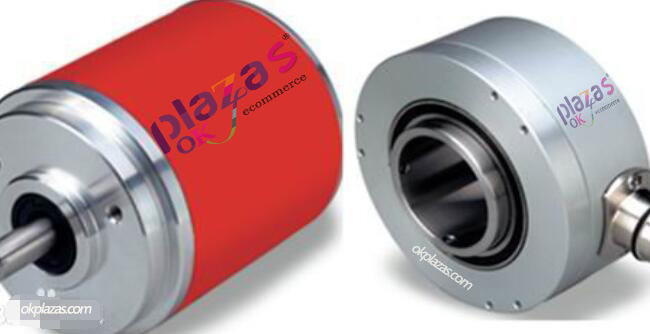
The servo motor encoder is a sensor installed on the servo motor to measure the magnetic pole position and the rotation angle and speed of the servo motor. From the difference of physical media, the servo motor encoder can be divided into photoelectric encoder and magnetoelectric encoder. In addition, the resolver is also regarded as a special servo encoder. Basically, the photoelectric encoder is used in the market. However, as a rising star, the magnetic encoder has the characteristics of reliability, low price, and anti-pollution. It can catch up with the photoelectric encoder. trend.
The basic function of the servo encoder is the same as the ordinary encoder. For example, the absolute type has A, A reverse, B, B reverse, Z, Z reverse and other signals. In addition, the servo encoder also has the same as the ordinary encoder. The difference between the servo motors is that most of the servo motors are synchronous motors. When the synchronous motor is started, the magnetic pole position of the rotor needs to be known, so that the servo motor can be started with a strong torque. This requires several additional signals to detect the current position of the rotor, such as The incremental type has UVW and other signals. Because of these signals for detecting the rotor position, the servo encoder is a bit complicated, so that most people don’t understand its reasoning, and some manufacturers deliberately mask some signals. , The relevant information is not complete, it adds to the mystery of the servo motor encoder.
Since the phases A and B differ by 90 degrees, the encoder's forward and reverse rotation can be judged by comparing the phase A or the B phase. The zero reference position of the encoder can be obtained through the zero pulse.
The materials of the encoder code disc are glass, metal, plastic. The glass code disc is deposited on the glass with very thin scribe lines, which has good thermal stability and high precision. The metal code disc is directly engraved with through and impassable lines and is not fragile. However, due to the certain thickness of metal, the accuracy is limited, and its thermal stability is one order of magnitude worse than that of glass. Plastic code discs are economical, and their cost is low, but accuracy, thermal stability, and life are worse. .
Resolution—The number of open or dark engraved lines provided by the encoder per 360 degree rotation is called resolution, which is also called resolution indexing, or directly called the number of lines, generally at 5 to 10,000 lines per revolution.
Servo motor encoder type
With the development of industrial production technology, advanced production equipment will be used in production. An important part of these production equipment is the servo motor encoder. The encoder is a kind of instrument equipment that compiles and converts the signal. So what are the main classifications of servo motor encoders? The following is a detailed introduction.
Servo motor encoders are classified according to the engraving method of the code disc: (there are many encoder classification methods, just talk about the commonly used classification)
1. Absolute encoder: There are several concentric code discs along the radial direction on its circular code disc, and each track is composed of light-transmissive and opaque fan-shaped areas. The sector trees of adjacent code channels are Double relationship, the number of code channels on the code disc is the number of binary digits. On one side of the code disc is the light source, and on the other side there is a photosensitive element corresponding to each code channel. When the code disc is in different positions, each The photosensitive element converts the corresponding level signal according to whether it receives light or not to form a binary number.
2. Incremental encoder principle: every time the shaft rotates through the specified unit angle, it sends out a pulse signal (there is also a sinusoidal signal, which is then subdivided and chopped to produce higher pulses), usually A, B, C three-phase output, A and B two phases are mutually delayed by 4 cycles of pulse output. According to the delay relationship, the forward and reverse can be judged. By using the rising and falling edges of the A and B phases, the frequency can be doubled and quadrupled. Phase Z is a single-turn pulse, that is, one pulse is sent out every turn.
-
The principle and application field of Autonics panel products (handling)
 June 12, 2021
 -
New product launch SRH1 series single-phase SSR with integrated heat sink
 June 12, 2021
 -
New product launch SRH1 series single-phase SSR with integrated heat sink
 June 12, 2021
 -
Otto protection grade IP69K new product launched Ø18mm cylindrical (SUS316L housing) photoelectric sensor BRQT series
 June 12, 2021
 -
Autonics adds shading motion mode sensor
 June 12, 2021