Siemens dual power automatic transfer switch 3KC series manual
Siemens dual power automatic transfer switch 3KC series manual
Introduction of Siemens dual power automatic transfer switch 3KC series
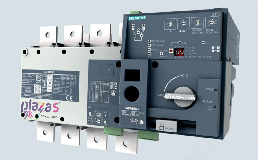
The Siemens 3KC4 and 3KC8 series dual-power automatic switching switch can be used to ensure a continuous supply of electricity. The appliance can reliably switch between the main source and the backup source, so it can be supplied from the emergency source in the event of a common power failure. The 3KC4 and 3KC8 series have three switch positions to maximize the stability of the load power supply, thus minimizing power interruption events.
◆3KC4: Dual power remote control transfer switch (RTSE); Current rating 250... 3200 a; Number of poles 3, 4; Application of regional power grid/power grid, power grid/generator.
◆3KC8: Dual power automatic transfer switch (ATSE); Current rating 250... 3200 a; Number of poles 3, 4; Application of regional power grid/power grid, power grid/generator.
Siemens 3KC4 and 3KC8 series dual power automatic switching switch can maintain continuous power supply, with the following main characteristics:
◆ Reliable conversion can be made between two power grids;
◆ Easy installation and open circuit conversion;
◆ The power outage time can be reduced to the minimum;
◆ 3-pole and 4-pole design;
◆ Current rating 250A to 3200A;
◆ The standard handle can be used for conversion;
◆ Abundant accessories and spare parts;
◆ Programming process only requires 5 steps (3KC8 only);
◆ Suitable for all load types, including high sensitive load (AC-33);
◆ Padlock can be placed at the position of 0(OFF) to ensure the safety of maintenance work.
◆ Control signal for starting/stopping generator, and generator and dual power automatic transfer switch testing with or without load (only 3KC8).
The Siemens 3KC4 and 3KC8 series dual power automatic switch can be used in all areas requiring continuous power supply as follows:
◆ Public facilities;
◆ Data center (data/server room);
◆ Shopping center;
Mixer airport;
In pieces the subway;
◆ Continuous working production line;
◆ Electric machine room;
The mixer pump.
Siemens dual power automatic transfer switch 3KC series structure
The configuration of 3KC4 dual-power remote control transfer switch (RTSE) and 3KC8 dual-power automatic transfer switch (ATSE) is shown in the figure below.
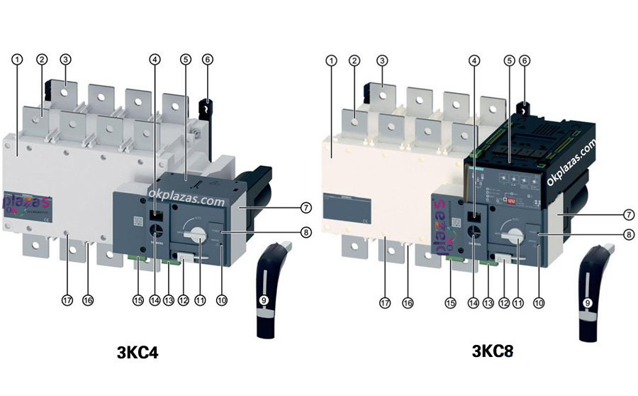
Switching device;
The connection terminal of the main source (source I);
The connection terminal of the alternate source (source II);
The relevant indication of the selected source: O=OFF/I= source I/II= source II;
For 3KC4: power interface cover plate, for 3KC8: electronic module (above the power interface);
Components for installation;
Motor operating mechanism;
Is "power" LED;
Pet-type insert handle for manual switching;
"Warning" LED;
⑪ mode selection switch (manual/automatic);
⑫ padlock.
⑬ 4-way output to "switch position" (I/O/II) instructions, "products available" instructions;
⑭ plug-in handle interface;
⑮ 5 road input, is used to position command (I/O/II), activate the remote control, fire strong cut orders;
⑯ terminal cover/alternate with the installation of partition slot;
⑰ strips fixed position.
The Siemens 3KC8 dual power Automatic switching switch (ATSE) is based on the 3KC4 (RTSE) switching switch. Unlike the 3KC4, the 3KC8 incorporates an additional electronic module. The electronic module can monitor two sources as well as the automatic transfer switch. In addition, the electronic module also supplies power to the 3KC8 transfer switch.
The structure of the electronic mode-operating mechanism control panel is shown in the figure below.
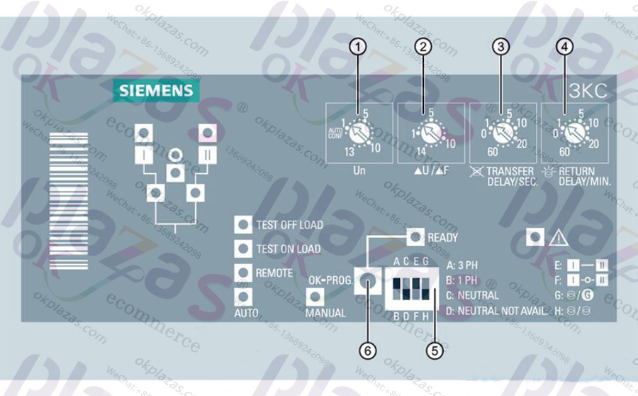
Potentiometer 1: Pre-setting of line voltage/frequency (automatic configuration, 1 to 13);
Potentiometer 2: Pre-setting of voltage/frequency thresholds (1 to 14);
Potentiometer 3: Pre-setting of conversion time delay in case of power failure (0 to 60s);
Potentiometer 4: Pre-setting of return conversion time delay (0 to 60min) when the power supply is restored;
DIP switch for configuration;
"Ok-prog" button: Save the current Settings.
The structure of the electronic module - Indicator (LED) panel is shown below.
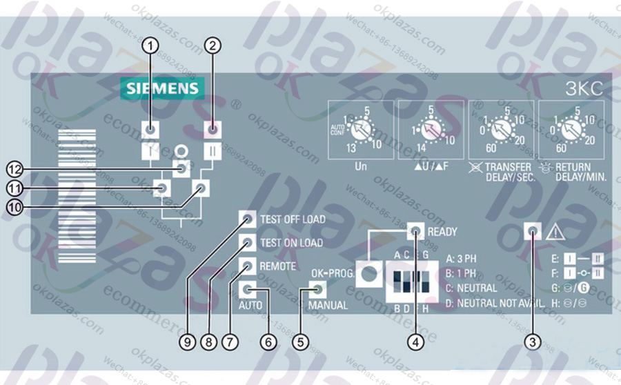
Availability source I: If source I is available and within allowable tolerances, the light is always green.
Availability source II: If source II is available and within allowable tolerances, the light is always green.
Fault indicator: if there is an external fault (for example, the neutral line is not in the correct position), the red light flashes. If the electronic module has internal failure, the red light will always be on.
"Ready" mode: indicates the working state of the transfer switch: if the dual-power automatic transfer switch is in "automatic" mode and is ready for source conversion, the green light will always be on. If the current setting has not been saved or a new change has been made, the green light flashes.
"Manual" mode: if the dual-power automatic transfer switch is in "manual" mode, the yellow light will always be on.
"Automatic" mode: indicates the activation state of "automatic" mode. If the Siemens dual power automatic transfer switch is in "automatic" mode and no counter is working, the green light will always be on. If you are in "auto" mode and the counter is working, the green light flashes.
"Remote" mode: if the switch is in remote control mode (through input control), then the yellow light is always on.
Today "with load test" mode: if Siemens dual power automatic switch in "with load test" mode, yellow light is always on.
(9) Pet-free mode: If the change-over switch is in pet-free mode, the light will always be yellow.
Position II indicator: If the switch is in position II, it will turn green.
⑪ position I instructions: if the switch is in position, I have a green light normally on.
⑫ position "0" indicates: if the switch is in position "0" (OFF), at a yellow light normally on.
Siemens dual power automatic transfer switch 3KC series parameters
Dual power transfer switches 3KC4 and 3KC8 have 10 current ratings respectively. The following figure lists the different types of switch by current rating.
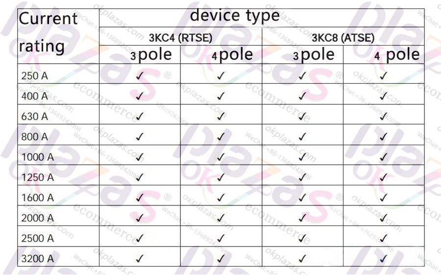
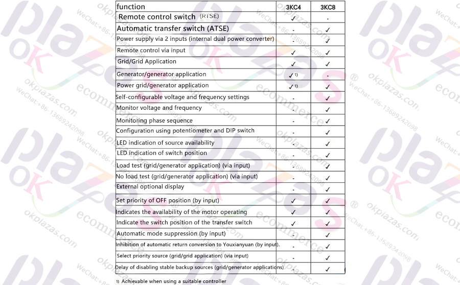
Dual 3KC4 and 3KC8 power transfer switches provide the following features to maintain power supply.
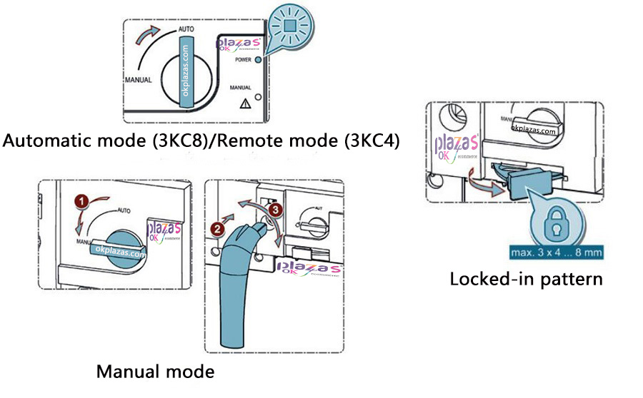
Siemens dual power automatic transfer switch 3KC series operation The performance range of Siemens 3KC4 and 3KC8 switches includes three operating modes in principle, as shown in the figure below.
◆ Remote mode
Enable remote mode of 3KC4 or 3KC8 changeover switch through input 312-317 on motor operating mechanism. Switch the changeover switch to different switch positions through these inputs.
For Siemens 3KC8 dual power automatic switching switch: the automatic mode of the electronic module can be disabled by closing the contacts 312 and 317 on the motor operating mechanism, and the 3KC8 switching switch can be used as a remote switching switch (RTSE).
◆ Activate remote mode
1.Switch the switch on the motor operating mechanism from the "manual" position to the "automatic" position to switch from the manual operation to the remote mode, and the "Power" LED will light up.
2. Close input 312 and 317, and input 313-316 can be used to control the conversion operation.
The "remote" LED on the electronic module lights up and the "automatic" LED goes out.
Note: Remote mode of Siemens dual power automatic transfer switch cannot be activated in these cases: the handle is located in the assembly and padlock the transfer switch (latching mode) is used.
◆ Manual operation
When the device is in "manual operation" mode, the transfer switch can be manually changed to the switch position using the attached handle, and the rotation direction can be identified by the mark on the handle. For example, manual operations can be activated in an emergency, or manual operations can be activated for maintenance work.
● Remote control using input (312-317) and automatic mode of electronic module (3KC8 only);
● Connection handle is allowed;
● If the handle is not connected, allow padlock locking (latching mode).
◆ Set "Manual" mode
1. Switch the switch on the motor operating mechanism from the "automatic" position to the "manual" position to switch from the remote/automatic mode (3KC8 only) to manual operation.
2.Connect the handle, the "power" LED and warning LED on the motor operating mechanism will light up, and the "manual" LED on the electronic module will also light up on the Siemens 3KC8 dual power automatic transfer switch.
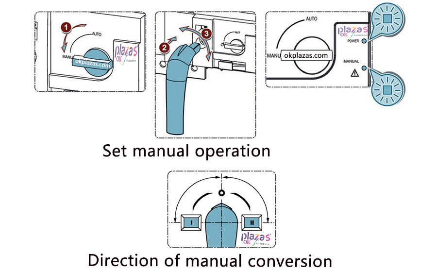
3. Rotate the handle clockwise/counterclockwise 90° according to the switch position for conversion.
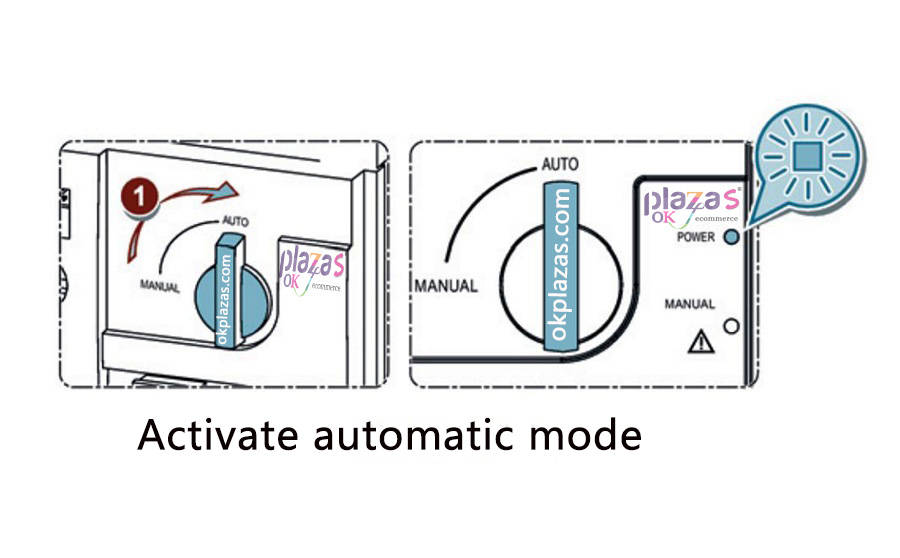
◆ Automatic mode (3KC8 only)
In automatic mode, the 3KC8 transfer switch is controlled by the automatic system of the electronic module. Depending on the availability of the source, the system converts the switch to a different switch position. To enable automatic conversion, the electronic module must be programmed according to the source requirements.
● Activate automatic mode of controller and electronic module;
● Disable latching mode;
● Prevent connecting handle.
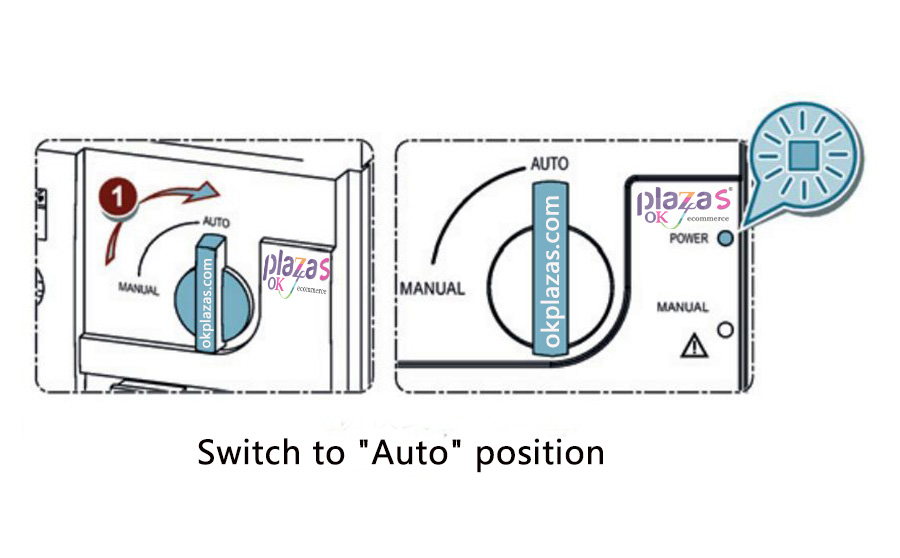
◆ Set automatic mode
1.Switch the switch on the motor operating mechanism from the "manual" position to the "automatic" position to switch from manual operation to automatic mode. The "power" LED on the motor operator is always green, the "automatic" LED on the electronic module is always green or flashing (depending on the default setting associated with the timer), and the "ready" LED on the electronic module is always green.
Note: Remote mode cannot be activated in these cases: the handle is located in the assembly and padlocks the dual power automatic transfer switch (latching mode).
-
The principle and application field of Autonics panel products (handling)
 June 12, 2021
 -
New product launch SRH1 series single-phase SSR with integrated heat sink
 June 12, 2021
 -
New product launch SRH1 series single-phase SSR with integrated heat sink
 June 12, 2021
 -
Otto protection grade IP69K new product launched Ø18mm cylindrical (SUS316L housing) photoelectric sensor BRQT series
 June 12, 2021
 -
Autonics adds shading motion mode sensor
 June 12, 2021