Understanding stepper drives
Understanding stepper drives
We know that a stepper motor is composed of a stator and a rotor. The stator winding generates an induced magnetic field after energization. The induced magnetic field interacts with the rotor to make the rotor rotate through a certain angle. By controlling the stator winding to be energized periodically and alternately, the stepper motor can be controlled to move forward step by step. The periodic control of the rotor coil of the stepper motor needs a special controller to achieve, and this controller is the stepper driver we are going to introduce today.
This lesson will introduce the following:
1) What is a stepper driver?
2) Wiring and setting of stepper driver;
3) Stepper driver subdivision drive setting;
4) Supplementary content of stepper motor;
1. What is a stepper driver?
The stepper driver is a power amplifier that drives the stepper motor to run. It can receive the control signal sent by the controller (PLC/SCM, etc.) and control the stepper motor to rotate through the corresponding angle/number of steps. The most common control signal is a pulse signal. The stepper driver controls the stepper motor to run one step after receiving a valid pulse. The stepper driver with subdivision function can change the inherent step angle of the stepper motor, achieve greater control accuracy, reduce vibration and increase output torque; in addition to pulse signals, stepper drivers with bus communication function can also receive the bus The signal controls the stepper motor to perform corresponding actions.
2. Wiring and setting of stepper driver
At present, there are many stepper drives on the market. The drives of various manufacturers have similar interfaces, all have signal, power, motor and other wiring terminals; there are dial switches for output current and subdivision drive settings. This section takes LeadShine's DM542 stepper driver as an example to introduce the wiring and settings of the next stepper driver.
DM542 is a two-phase stepper motor driver introduced by Lei Sai. It adopts pulse control method, supports 8-level current and 16-level subdivision drive; input voltage range: DC 20V~50V, output peak current range: 1.0~4.2 A; the following one
The picture shows the appearance of DM542:
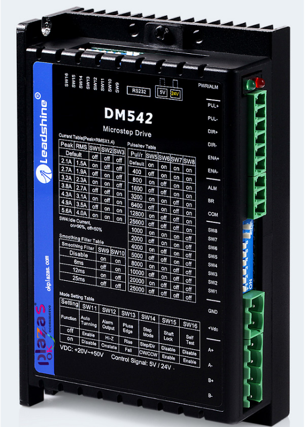
As can be seen from the picture, the DM542 stepper driver includes control signal terminals, power terminals, motor wiring terminals, output current settings and subdivision drive settings DIP switches.
2.1, control signal terminal
The control signal terminal is connected with PLC, single-chip microcomputer or other controllers to receive the pulse, direction and enable control signals sent by the controller.
2.1.1, pulse signal (Pulse)
The pulse signal has two terminals: PUL+ and PUL-. "PUL+" connection pulse signal positive
Pole, "PUL-" is connected to the negative pole of the pulse signal; the pulse signal is the voltage difference between "PUL+" and "PUL-"
To measure; DIP switch SW13 can set the effective edge of the pulse, the default (SW13=OFF) rising edge is effective;
2.1.2, direction signal (Direction)
The direction signal has two wiring terminals: DIR+ and DIR-. "DIR+" connects the direction signal positive, and "DIR-" connects the direction signal negative; the initial running direction of the stepper motor is related to the wiring of the motor windings, any group of windings can be interchanged (for example: A+ and A- interchange) The initial running direction of the motor; the direction change of the motor during operation can be controlled by the direction signal. In order to ensure the reliable commutation of the stepper motor, the direction signal should be established at least 5us earlier than the pulse signal;
2.1.3, enable signal (Enable)
The enable signal is used to enable or disable the output of the drive. There are two wiring terminals: ENA+ and
ENA-. "ENA+" is connected to the positive pole of the enable signal, and "ENA-" is connected to the negative pole of the enable signal; when the "ENA+" signal is on, the driver will cut off the power of each phase of the stepper motor and make it in a free state, which does not respond to pulse signals ;
Note: The input voltage value of pulse signal, direction signal and enable signal can be set by sliding switch. There are two choices of DC 5V and DC 24V. The factory default is DC 24V;
2.1.4, alarm signal (Alarm)
Drive fault signal output, used to connect to the input channel of the PLC/controller. The factory defaults that ALM and COM are in the on state under normal conditions, and they are in the off state when the driver alarms; it can be set through the DIP switch SW12;
2.1.4. Brake signal (Brake): Brake signal input of stepper motor;
2.1.5. COM: the common terminal of alarm signal and brake signal;
2.2, power interface
The power interface includes 2 terminals: +Vdc, GND, of which: +Vdc: DC power supply positive, voltage range:
+20V~+50V, +24V~+48V is recommended;
GND: negative pole of DC power supply;
2.3. Motor wiring terminals Motor wiring terminals include: A+, A-, B+, B-, of which:
A+ and A- are the two terminals of the A-phase winding of the stepper motor;
B+ and B- are the two terminals of the B-phase winding of the stepper motor;
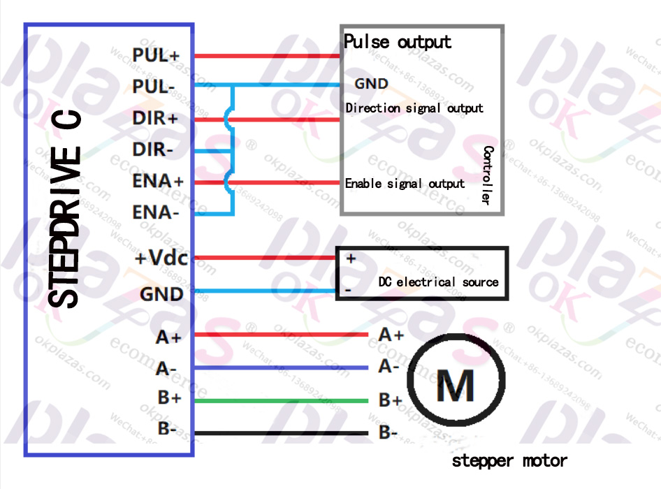
The following picture is the wiring diagram of the stepper motor driver:
2.4. Current setting of stepper motor
There are 8 DIP switches (SW1~SW8) in the middle of DM542 stepper driver, among which SW1~SW3 are used to set working current (dynamic current); SW4 is used to set static current (quiescent current); SW5~SW8 are subdivision settings (It will be described in detail in Section 3);
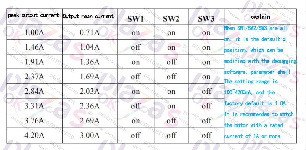
2.4.1, working current setting
By setting the current output dial switch of the stepper driver, the output current of the driver can be changed. The SW1~SW3 dial switch settings of DM542 are shown in the figure below:
When the output current set by the stepper driver is greater, the output torque of the stepper motor connected
Bigger. However, excessive current will cause the motor and drive to heat up, and in severe cases, it may damage the motor or drive. Therefore, it is recommended to follow the following principles when setting the current of the stepper drive:
Four-wire motor: set the output current equal to or slightly less than the rated current of the motor; six-wire motor high torque mode: set the output current equal to 50% of the rated current of the motor with unipolar connection;
Six-wire motor high speed mode: set the output current equal to 100% of the rated current of the motor with unipolar connection;
For example: suppose you want to use DM542 to drive a Leisai 42CM06 stepper motor, the rated current of the motor is 2.5A, we use the output average current 2.36A gear, set SW1=OFF,
SW2=ON, SW3=OFF;
Also note: the type of movement of the stepper motor and the length of its residence time will affect its heating
the amount. Therefore, in actual use, the output current should be appropriately adjusted according to the heating of the motor. In principle, if the surface temperature of the motor is lower than 40 degrees after running for 15 to 30 minutes, the current setting value can be appropriately increased to increase the output torque; but if the temperature rise is too high (>70 degrees), the current setting value should be reduced;
2.4.2, Quiescent current setting
The DIP switch SW4 can be used to set the output current of the driver when the stepper motor is at a standstill. By default, SW4=OFF, it means that the drive changes the output current to 50% of the peak current after 0.4 seconds without receiving the pulse, which can reduce the heating of the drive and the motor; if SW4 is set to ON, the motor is at a standstill In the state, the output current of the driver is 90% of its peak current;
3. Subdivision drive settings
3.1. What is a subdivision driver?
Stepping motors are marked with "intrinsic step angle" when they leave the factory. For example, the inherent step angle of a motor is
0.9 degree/1.8 degree means that the motor will rotate by 0.9 degree each time in half-step work, and the whole step is 1.8 degrees. In many precision control occasions, the inherent step angle cannot meet the requirements of control accuracy, and people hope to complete an inherent step angle in many steps. This driving method that divides the inherent step angle into many steps is called "subdivision driving". The driver that can realize subdivision drive is called "subdivision drive".
3.2. Advantages of subdivision drive
The subdivision drive divides the inherent step angle into several equally, reducing the step angle of each step
It improves the step uniformity and control accuracy; low-frequency oscillation is an inherent characteristic of stepping motors, and the subdivision drive increases the rotation frequency of the motor and can reduce the vibration of the motor.
Dynamic; subdivision drive can effectively reduce torque fluctuations and increase output torque;
3.4, subdivision drive settings
Take DM542 as an example, the driver provides four DIP switches (SW5~SW8) to set the subdivision drive, as shown in the figure below:
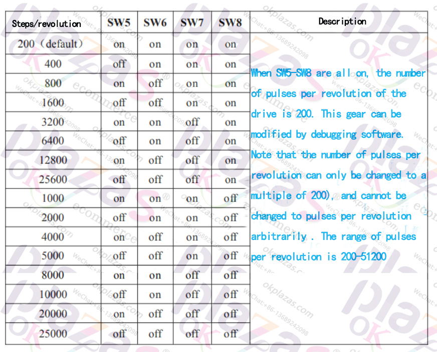
Suppose we want to set the motor to 3200 steps/revolution (that is, 3200 pulse signals are required for each revolution.
Number), the DIP switch settings are as follows: SW5=ON, SW6=ON, SW7=OFF, SW8=ON
4. Supplementary content of stepper motor
Question: What does the 42 series and 57 series stepper motors usually mean?
Answer: The 42 series and 57 series mentioned here refer to the frame number of the stepper motor, that is, the size of the frame of the stepper motor. The 42 series stepping motor indicates that the size of the motor frame is 42cmx42cm. For example, the following figure is a cross-sectional view of the base of Leisai 42 stepper motor:
According to the frame number, common stepper motors include 42 series, 57 series, 86 series, 110 series, etc.;
-
The principle and application field of Autonics panel products (handling)
 June 12, 2021
 -
New product launch SRH1 series single-phase SSR with integrated heat sink
 June 12, 2021
 -
New product launch SRH1 series single-phase SSR with integrated heat sink
 June 12, 2021
 -
Otto protection grade IP69K new product launched Ø18mm cylindrical (SUS316L housing) photoelectric sensor BRQT series
 June 12, 2021
 -
Autonics adds shading motion mode sensor
 June 12, 2021