Understanding the problem of encoder interference
Understanding the problem of encoder interference
1. The problem of pulse loss caused by mechanical installation and other reasons
//
There is a certain corresponding relationship between the frequency of the encoder signal drop and the actual value of the motor speed. Generally, there is a problem with the grating signal of the encoder at some positions.
The main reason for such problems is that mechanical damage such as knocks and collisions occurred during the installation of the encoder, which affects the photoelectric system of the encoder and causes related problems.
Solve the problem: due to hardware damage, only replacement!
//
2. The encoder signal is unstable due to electromagnetic interference
//
The clock signal of the SSI encoder has a "burr" when the inverter is enabled: interference source: inverter; coupling path: strong alternating electric field coupled to the encoder signal loop; victim: encoder signal.
The solution of the problem: On the one hand, it deals with the reliable grounding of the shielding layer of the signal cable; on the other hand, it isolates the space from the interference source (frequency converter and power).
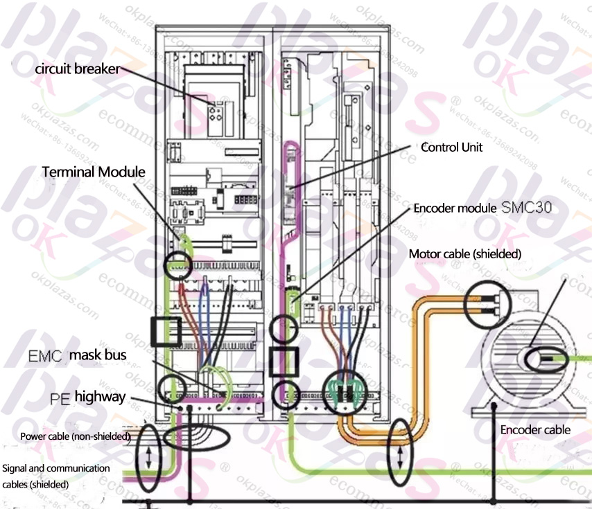
Typical schematic diagram of EMC installation of drive system
//
3. The problem of high frequency characteristics of long-line transmission of encoder
//
The output frequency of the pulse signal of the encoder is linearly proportional to the speed. As the speed increases, the output signal frequency of the encoder increases. From the perspective of failure phenomena, this is a typical problem caused by poor high-frequency characteristics of long-term signal transmission.
Through the investigation of the line and cable, the problem is basically locked on the encoder transmission line.
The solution of the problem: improve the output characteristics of the signal cable; reduce the transmission distance of the high-frequency signal; the spatial arrangement of the signal cable; enhance the output load capacity of the encoder. Based on the actual situation on site, after rearranging the transmission distance of the signal cable (reduced from 130m to 90m), the signal transmission distance is greatly reduced, and the characteristics of long-line high-frequency signal transmission are greatly improved.
//
4. Dealing with related noise problems of analog tachometer motors
//
When the system is not running the feedback signal of the speed measuring motor, there are irregular numerical fluctuations. Because the speed regulator adopts the time PI control, it is a non-difference system. In the case of a given zero speed, the feedback signal is at the "0" attachment The change caused the system to fail to stop normally, causing jitter.
The solution of the problem: For the background noise superimposed on the analog signal and the drift signal in the analog circuit, it is generally high-frequency noise, which can be processed by software or hardware filtering; for the signal cable, twisted-pair shielded cables should be used, and the cable The shielding layer must be reliably grounded at both ends; but when you need to pay attention, double-ended grounding will superimpose low-frequency "hum" ground circulating noise in the signal for low-frequency noise crosstalk. On the one hand, the shielding layer must be reliably grounded on the drive side, and the field side It can be reliably grounded through MKT capacitors (capacity 10nF/100V); in terms of software, related problems can also be solved by methods such as PIP control switching of the speed regulator.
We can see that when solving the interference problem of the encoder, we should start with the system design and select the appropriate equipment according to the actual field application and environmental conditions. The encoder system is generally affected by common mode and differential mode interference. We can choose differential type encoders, such as bipolar type. For differential mode interference, cable selection, line routing, power system isolation processing, signal reference, etc. require careful design and layout.
Due to the complexity of EMC problems, the analysis and handling methods may be different and inadequate. For the analysis of actual problems, I hope that we can provide insights and in-depth discussions to facilitate further processing of actual engineering problems.
-
The principle and application field of Autonics panel products (handling)
 June 12, 2021
 -
New product launch SRH1 series single-phase SSR with integrated heat sink
 June 12, 2021
 -
New product launch SRH1 series single-phase SSR with integrated heat sink
 June 12, 2021
 -
Otto protection grade IP69K new product launched Ø18mm cylindrical (SUS316L housing) photoelectric sensor BRQT series
 June 12, 2021
 -
Autonics adds shading motion mode sensor
 June 12, 2021