What are the circuit principles and classification applications of photoelectric rotary encoders?
What are the circuit principles and classification applications of photoelectric rotary encoders?
What are the circuit principles and classification applications of photoelectric rotary encoders?
What are the circuit principles and classification applications of photoelectric rotary encoders?
The photoelectric encoder is an angle (angular velocity) detection device. It converts the angle input to the shaft into the corresponding electric pulse or digital quantity by using the photoelectric conversion principle. It has the advantages of small size, high precision, reliable work, and digital interface. . It is widely used in devices and equipment that need to detect angles such as CNC machine tools, rotary tables, servo drives, robots, radars, and military target determination.
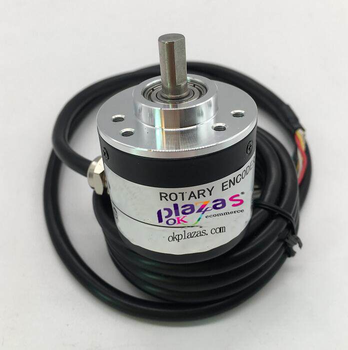
The photoelectric encoder is mainly composed of a grating disc and a photoelectric detection device. In the servo system, the grating disc and the motor are coaxial to cause the rotation of the motor to drive the rotation of the grating disc, and then output several pulse signals through the photoelectric detection device, according to each signal The number of pulses per second can calculate the current motor speed. The code disc of the photoelectric encoder outputs two optical codes with a phase difference of 90 degrees, and the rotation direction of the motor can be judged according to the state of the dual-channel output optical codes.
Working principle: When the shaft of the photoelectric encoder rotates, both wires A and B produce pulse output, and the phase angle of the phase A and B pulses is 90 degrees. From this, the rotation direction of the photoelectric encoder and the motor speed can be measured. If the A-phase pulse is ahead of the B-phase pulse, the photoelectric encoder is forward, otherwise it is reverse. The Z line is the zero pulse line, and the photoelectric encoder generates one pulse per revolution. It is mainly used for counting. Line A is used to measure the number of pulses, line B and line A can be used to measure the direction of rotation.
N is the motor speed
n=ND test-ND theory
For example: the speed of our car is 1.5m/s, the diameter of the wheels is 220mm, C=D*Pi, the motor is controlled at 21.7 revolutions per second, according to the index of the servo system, the motor speed is set to 1500 revolutions per minute, so it can be calculated properly When ND=21.7*60=130 rpm, the number of pulses output by the optical code disc per second is:
PD=130600/60=1300 pulses
When the measured number of pulses deviates from the calculated standard value, the incremental voltage △U output to the servo system can be calculated according to the corresponding relationship between the voltage and the number of pulses, and after D/A conversion, the increase is calculated. Measure the number of pulses and subtract it later.
When the running time is longer, the route is longer, and it deviates more from our pre-made route. At this time, the system starts the position loop, by continuously measuring the number of pulses output by the photoelectric encoder per second, and comparing it with the standard value PD (ideal value), calculating the increment △P and converting it into the corresponding D/A Output digital quantity, reduce the number of pulses output to a motor through the controller, subtract the increment from the original output voltage, force the motor speed to drop, and stop adjusting when the measured △P is approximately zero. The motor speed is always controlled within the allowable range.
According to the detection principle, encoders can be divided into optical, magnetic, inductive and capacitive. According to its scale method and signal output form, it can be divided into two types: incremental and absolute.
First: incremental encoder
Incremental optical encoders can obtain sine wave output by combining the indicating scales and perform displacement measurement at the same time. The circular plates are equally spaced slits and reference slits, with simple structure and easy manufacture, low price, and the zero point can be set to any angle position. On the slit chart, there are slits at equal intervals. It is detected that the slits with the same interval are equipped with light sources, lenses, and light detector components to detect signals. Incremental counting method is to establish the origin at any point, and then digitally indicate the displacement or angle change from the origin.
Second: absolute encoder
The absolute encoder is a sensor that directly outputs digital quantities. There are several concentric code tracks along the radial direction on its circular code disc. Each track is composed of light-transmissive and opaque sectors. The fans of adjacent code channels The number of zones is a double relationship. The number of code channels on the code wheel is the number of binary digits. On one side of the code wheel is the light source, and the other side has a photosensitive element corresponding to each code channel; when the code wheel is in different positions When, each photosensitive element converts the corresponding level signal according to whether it receives light or not, and forms a binary number. The characteristic of this kind of encoder is that no counter is needed, and a fixed digital code corresponding to the position can be read out at any position of the shaft. Obviously, the more code channels, the higher the resolution. For an encoder with N-bit binary resolution, the code disk must have N code channels. At present, there are 16-bit absolute encoder products in China.
The absolute encoder uses natural binary or cyclic binary (Grey code) method for photoelectric conversion. The difference between an absolute encoder and an incremental encoder is the transparent and opaque line pattern on the disc. The absolute encoder can have several codes, and the absolute position can be detected according to the code on the read code disc. The coding design can adopt binary code, cyclic code, two's complement code, etc. Its characteristics are: the absolute value of the angle coordinate can be read directly; there is no cumulative error; the position information will not be lost after the power is cut off. But the resolution is determined by the number of bits in the binary system, which means that the accuracy depends on the number of bits. There are currently 10 bits, 14 bits, etc.
-
The principle and application field of Autonics panel products (handling)
 June 12, 2021
 -
New product launch SRH1 series single-phase SSR with integrated heat sink
 June 12, 2021
 -
New product launch SRH1 series single-phase SSR with integrated heat sink
 June 12, 2021
 -
Otto protection grade IP69K new product launched Ø18mm cylindrical (SUS316L housing) photoelectric sensor BRQT series
 June 12, 2021
 -
Autonics adds shading motion mode sensor
 June 12, 2021